ISO9001:2008 Quality Management System Authentication CE Authentication EDS1000 series EDS1100/EDS1300 series Universal inverter Ver.4.0 Service manual SHENZHEN ENCOM ELECTRIC TECHNOLOGIES CO.,LTD.
Print version:V4.0-A5 Foreword Encom products are designed and produced according to EN61800-5-1: 2007, EN61010-1:2010; EN61800-3: 2004+A1:2012 standards under ISO9001:2008 quality management system. Thank you for purchasing EDS1000 series multi-function universal inverter from our company Shenzhen Encom Electric Technologies CO., LTD. 1.
control method, independently form dual-frequency digital PID control system, automatically identify the diameter of reel roll, the mechanical transmission ratio, cable diameter, automatically adjust the PID parameters, track the speed of the host, that is to pole zero of the tension balance when it powers on (middle point), is a real sense of the fool-type inverter special for drawing machine. As long as the correct general electrical wiring, you can work.
CONTENTS 1 Safety information and use notice points 1.1 Safety precautions 1.2 Use range 1.3 Use notice points 1.4 Scrap notice points 2 3 Type and specification of the inverter 1 1 2 2 3 4 4 2.1 Incoming inverter inspect 2.2 Type explanation 2.3 Nameplate explanation 2.4 Series type explanation 2.5 Appearance and parts name explanation 2.6 Outer size and gross weight 2.7 Outer size of key board and its fixing box 6 6 8 2.
3.6.2 Explanation for control panel terminal 20 3.6.3 Analog input output terminal wiring 3.6.4 Communication terminal wiring 3.7.1 Restraining to noise disturbance 23 25 27 27 3.7.2 Locale wiring and earthing 29 3.7.3 Relation of long-distance wiring and current leak 3.7 Installation guide for anti-jamming and the countermeasure 3.7.4 Installation demand for electromagnetic on-off electronic device 4 Run and operation explanation for inverter 4.1 Run of inverter 4.1.
.2 Start, stop, braking function parameter group:F1 6.3 Auxiliary run function parameter group: F2 6.4 Closed-loop run function parameter group: F3 6.5 Simple PLC function parameter group:F4 6.6 Terminal correlative function parameter group: F5 6.7 Traverse special function parameter group: F6 6.8 Frequency provision function parameter group: F7 6.9 Motor and vector control parameter group: F8 6.10 Protection function parameter group:F9 6.11 Failure record function parameter group: Fd 6.
Modbus communication protocol 128 Appendix1 EDS1100 drawing machine inverter manual 135 154 11 Appendix2 The manual of EDS1300 middle frequency inverter Appendix3 Serial port RS485 communication protocol (need customized special process) Appendix4 Braking resistance 168 178
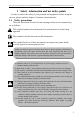
www.enc.net.cn/en Tel/Fax:86-755-26984485/26985120 1 1 Safety information and use notice points Safety information and use notice points In order to ensure the safety of your personal and equipment, before using the inverter, please read this chapter of contents conscientiously. 1.1 Safety precautions There are three kinds of safe relevant warnings in this service manual, they are as follows: ! This symbol explains items that need to be paid attention to when being operated.
www.enc.net.cn/en Tel/Fax:86-755-26984485/26985120 1 Safety information and use notice points (1) ! 1.2 It is prohibited that connect AC 220V signal to control ends except TA, TB, TC, otherwise have danger of damaging property. (2) If the inverter is damaged or without all parts, please don't install and operate it, otherwise have danger of fire or cause personnel to be injured.
www.enc.net.cn/en Tel/Fax:86-755-26984485/26985120 1 Safety information and use notice points inverter output and the motor, please guarantee the inverter is switched on/off without output, otherwise may damage the inverter. (8) The inverter may meet with mechanical resonance of the load within certain range of frequency output, can set up jumping frequency to evade.
www.enc.net.cn/en Tel/Fax:86-755-26984485/26985120 2 2.1 2 Type and specification of the inverter Type and specification of the inverter Incoming inverter inspect (1) Check if there is damage during transportation and inverter itself has damage or fall-off parts. (2) Check if parts presented in packing list are all ready. (3) Please confirm rated data of the inverter is in line with your order requirement.
www.enc.net.cn/en Tel/Fax:86-755-26984485/26985120 2.4 2 Type and specification of the inverter Series type explanation Table 2-1 series type explanation Inverter type (G: general with constant torque: P: special for blower water pump) EDS1000/1300-2S0004 Input voltage (V) EDS1000/1300-2S0007 Single phase 220V Rated power (KVA) Rated output current (A) Adapted motor (KW) 1.1 3 0.4 1.8 4.7 0.75 2.8 7.5 1.5 3.8 10 2.2 EDS1000-2S0037 5.6 17 3.7 EDS1000-2T0007 1.1 4 0.75 2.1 7 1.
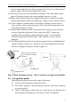
www.enc.net.cn/en Tel/Fax:86-755-26984485/26985120 2.5 2 Type and specification of the inverter Appearance and parts name explanation digital potentiometer LED display keypad LED display digital potentiometer Upper cover plate keypad connection terminal Control cable nameplate inlet bottom fitting hole ventilation hole Control cable inlet Power supply input end output end ventilation hole Fig. 2-3 Parts name sketch 2.
www.enc.net.cn/en Tel/Fax:86-755-26984485/26985120 Table 2-2 2 Type and specification of the inverter EDS1000-2S0004~EDS1000-4T0750P mounting size Fixing G.W. A B W H D D1 aperture (mm) (mm) (mm) (mm) (mm) (mm) (mm) (kg) Inverter type (G: general; P: special) EDS1000/1300-2S0004 EDS1000/1300-2S0007 EDS1000/1300-2S0015 EDS1000/1300-2S0022 EDS1000/EDS1100/1300-4T0007G/0015P Fig. 110 160 125 170 123.2 135.5 4 2 Fig a 140 215 155 230 155 164 5 3.
www.enc.net.cn/en Tel/Fax:86-755-26984485/26985120 2.7 2 Type and specification of the inverter Outer size of keypad and its fixing box (unit: mm) Fig.2-5 EN-KB5 outer size Fig.2-6 EN-KB5 hole size 152.5 160 94 87.5 4 Fig.2-7 EN-KB6 outer size 2.8 EN-KB6 hole size Product technic index and spec Item Rating volt., frequency Input Allowed work volt. range output 8 Fig.
www.enc.net.cn/en Tel/Fax:86-755-26984485/26985120 Frequency 0Hz-400Hz Over loading capacity Control mode Speed regulation range Start-up torque Running speed stable state precision 1: 100 150% of rating torque at 1 Hz frequency ≤±0.5% of rating synchronous speed Digital setting: max. frequency×±0.01%;analog setting: max.frequency×±0.5% Analog setting Frequency Digital setting resolution Exterior impulse precision : <100Hz 0.01Hz; ≥100Hz: 0.1Hz V/F curve (volt. frequency characteristic) 0.1% of max.
www.enc.net.cn/en Tel/Fax:86-755-26984485/26985120 pulse output channel Analog output channel Can display setting frequency, output frequency, output voltage, output current etc. Lock the button Lock all or part of the buttons(analog potentiometer can’t be locked) Protection function Over-current protection, over-voltage protection, lack-voltage protection, over-heat protection, over-load protection, etc.
www.enc.net.cn/en Tel/Fax:86-755-26984485/26985120 3 3.1 3 Installation and wiring Installation and wiring Installation ambient 3.1.1 Demand for installation ambient (1) Installed in drafty indoor place,ambient temperature within -10ºC~40ºC,need external compulsory heat sink or reduce the volume if temperature exceeds 40ºC. (2) Avoid installing in place with direct sunlight, much dust, floating fibre and metal powder. (3) Forbid to install in place with corrosive, explosible gas.
www.enc.net.cn/en Tel/Fax:86-755-26984485/26985120 3 Installation and wiring inverter Leading divider inverter Fig. 3-2 mounting of multiple inverters 3.2 Parts disassembly and installation 3.2.1 Key board disassembly and installation Mounting claw (1) Disassembly Let the forefinger press finger inlet on the keypad,depress fixing flexible plate on the top lightly, draw it outward, then Hook Mounting claw you can disassemble the keypad. (2) Assembly Fig.
www.enc.net.cn/en Tel/Fax:86-755-26984485/26985120 3 Installation and wiring (1) Disassembly First take off 2 screws at sides of the cover and move it a bit outward horizontally, then tilt it at 15 degree and draw it outward at direction shown in right figure, now you can take the cover off.
www.enc.net.cn/en Tel/Fax:86-755-26984485/26985120 ! 3 Installation and wiring (1) Before wiring, assure power supply is cut off completely for 10 minutes and all LED indicator light extinguished. (2) Before internal wiring, confirm that DC volt. Between main loop end P+ and P- fall down to below DC36V. (3) Wiring can only be done by professional person trained and qualified. (4) Before electrification, check if voltage grade of the inverter is in line with that of power supply volt.
www.enc.net.cn/en Tel/Fax:86-755-26984485/26985120 (5) Input side EMI filter Can use EMI filter to inhibit high-frequency conduction disturbance and emission disturbance from inverter power supply wire. (6) Output side EMI filter Can use EMI filter to inhibit emission disturbance noise and wire leakage current from output side.
www.enc.net.cn/en Tel/Fax:86-755-26984485/26985120 3.4.2 3 Installation and wiring Main loop terminal wiring For main loop input output terminal, see table 3-1.
www.enc.net.cn/en Tel/Fax:86-755-26984485/26985120 3 Installation and wiring U, V ,W R、S、T P+ PB EDS1000-4T0150G EDS1000-4T0185P R S T P+ PB P- U V W PU、V、W R、S、T note EDS1000-4T0185G ~ EDS1000-4T0550G EDS1000-4T0220P ~ EDS1000-4T0750P R EDS1000-7T0185G ~ EDS1000-7T1320G EDS1000-7T0220P ~ EDS1000-7T1600P P+ P P- R S P S T P P+ P- U V W PE P+ PU、V、W PE P+ P T P- U V W PE R、S、T U、V、W PE 3 phase AC output end 3 phase AC 380V input terminal DC volt.
www.enc.net.cn/en Tel/Fax:86-755-26984485/26985120 3.
www.enc.net.cn/en Tel/Fax:86-755-26984485/26985120 3.6 3 installation and wiring Control loop collocation and wiring 3.6.1 Location&function of terminal and slide switch: For location of terminal and slide switch on the CPU board, please see Fig.3-10. Function description of terminal provided for the user, please see Table 3-2, function and setup description of slide switch, please see Table 3-3,terminal CN1, CN3 and are for manufacturer’s use.
www.enc.net.cn/en Tel/Fax:86-755-26984485/26985120 3 installation and wiring Table 3-3 function description of slide switch provided for user Factory default Symbol Function JP7 YCI: 5V/10V voltage input mode selection : 0~5V voltage signal; JP8 VCI: 5V/10V voltage input mode selection : 0~10V voltage signal; JP9 CCI: current/voltage input mode selection : 0/4~20mA current signal; JP6 analog output terminal AO1 output current/voltage type selection 3.6.
www.enc.net.cn/en Tel/Fax:86-755-26984485/26985120 X4 X5 X6 X7 X8 +24V Multi-function input 4 X7, X8 can be set as H-speed impulse input port, Multi-function input 5 for detailed see Chapter 6 Section 6.6 terminal Multi-function input 6 function parameter(F5 group)input end function Multi-function input 7 description.
www.enc.net.cn/en Tel/Fax:86-755-26984485/26985120 Multifunction output end OC1 Open circuit collector output terminal 1 OC2 Open circuit collector output terminal 2 OC3 Open circuit collector output terminal 3 OC4 Open circuit collector output terminal 4 DO 3 installation and wiring Used for multi-function switch output terminal, for detailed see Chapter 6 Section 6.6 terminal function parameter (F5 group) output end function description.
www.enc.net.cn/en Tel/Fax:86-755-26984485/26985120 Table 3-6 Item symbol 3 installation and wiring CPU board JP1 terminal function name Function description TA Relay output terminal TB Inverter Normal: TB-TC closed, TA-TC open malfunction Malfunction: TB-TC open, TA-TC output relay closed TC 3.6.3 Spec TB-TC: always-closed, TA-TC: always-open Contact capacity: AC250V/2A (COSΦ=1) AC250V/1A (COSΦ=0.
www.enc.net.cn/en Tel/Fax:86-755-26984485/26985120 3 installation and wiring (3) YCI terminal accepts analog voltage signal input,wiring mode as follows: YCI current input EDS1000 +10V + 0~+10 JP7 VCI 0~5V Or 0~+5V ― Shielded wire close end grounded Fig.3-13 YCI volt.
www.enc.net.cn/en Tel/Fax:86-755-26984485/26985120 3 installation and wiring Analog current output Analog meter JP6 AO1 0~10V AO2 Analog voltage output GND JP6 4~20mA Fig.3-14 note 3.6.4 analog output terminal wiring (1) When inputing anglog signal,can connect filter capacitor or common module inductance between VCI and GND or between CCI and GND or between YCI and GND.
www.enc.net.cn/en Tel/Fax:86-755-26984485/26985120 3 installation and wiring (3) Connection between inverter RS485 interface and upper machine(with RS232 interface): RS232/RS485 converter Terminal explain 5Vpower positive Terminal explain Name Name TXD Receivingdata line RXD 5VPower ground GND Pin no.
www.enc.net.cn/en Tel/Fax:86-755-26984485/26985120 3.7 3 installation and wiring Installation guide for anti-jamming Main circuit of the inverter is composed of high-power semiconductor switch gear,so some electromagnetic noise will arise during work,to reduce or stop disturbance to environment,show you assembling method of inverter disturbance suppressing from many aspects such as disturbance suppressing, spot wiring, system grounding, leak current, usage of power supply filter etc.
www.enc.net.cn/en Tel/Fax:86-755-26984485/26985120 3 installation and wiring (2) Noise spread road ⑧ TV ② ⑥ ⑤ power supply ② ③ inverter ④ Wireless set meter ⑦ sensor ⑤ motor ① Fig.
www.enc.net.cn/en Tel/Fax:86-755-26984485/26985120 ⑥⑦⑧ 3 installation and wiring To prevent parallel or bundled power and weak conducting wire;should keep away from inverter mounted device to the best and its wiring should keep away from power wire of the inverter such as R, S, T, U, V, W etc.. Should pay attention to relative mounting place between device with strong electric field or strong magnetic field and the inverter, should keep distance and vertical intersection. 3.7.
www.enc.net.cn/en Tel/Fax:86-755-26984485/26985120 3 installation and wiring these electromagnetic on-off electronic device would bring lots of noise during work, so you should pay full attention to when installing them beside the inverter or in the same control chamber with the inverter and must install surge absorbing device as shown in Fig. 3-21. diode + 24VDC _ Voltage-sensible resistor Inverter or ~ other electric 220VAC apparatus ~ RC-filter ~ 220VAC Fig.
www.enc.net.cn/en Tel/Fax:86-755-26984485/26985120 4 4 Run and operation explanation for inverter Run and operation explanation for inverter 4.1 Run of inverter 4.1.1 Running order channels There are 3 kinds of order channel for controlling run action of the inverter such as run, stop, jog etc.: 0: keypad Control by key RUN , STOP , REV JOG on keypad(factory default).
www.enc.net.cn/en Tel/Fax:86-755-26984485/26985120 4.1.4 4 Run and operation explanation for inverter Run mode EDS1000 inverter have 6 kinds of run mode,following is in turn according to their priority: jog run→closed-loop run→PLC run→multisection speed run→ swing frequency run→common run. Shown as Fig.4-1.
www.enc.net.cn/en Tel/Fax:86-755-26984485/26985120 4 Run and operation explanation for inverter The inverter will come into closed-loop run mode when closed –loop run control effective parameter is set(F3.00=1). Namely carry on PID adjustment to specified value and feedback value(proportion integral differential calculation,see F3 group function code) and PID adjustor output is inverter output frequency.
www.enc.net.cn/en Tel/Fax:86-755-26984485/26985120 4.2 4 Run and operation explanation for inverter Operation and use of key board 4.2.1 Keypad layout Keypad is main unit for receiving command, displaying parameter. Outer dimension of EN-KB6 is as Fig.
www.enc.net.cn/en Tel/Fax:86-755-26984485/26985120 4.2.3 4 Run and operation explanation for inverter Analog potentiometer Be used to set frequency; when F0.
www.enc.net.cn/en Tel/Fax:86-755-26984485/26985120 4 Run and operation explanation for inverter supervision parameter in function parameter schedule graph of chapter 5). (2) run parameter display status The inverter enters into run status when receiving effective run command and normally parameter F3.28 decide which status supervision parameter to be displayed on the keypad. As shown in Fig.4-3 c,unit is displayed by rightward unit indicator light.
www.enc.net.cn/en Tel/Fax:86-755-26984485/26985120 4 Run and operation explanation for inverter (4) function code editing status ESC Under waiting, run or failure alarm status,press MENU key,can enter into editing status(If user password is set,can enter into editing status after inputting the password,see also FF.00 description and Fig.4-10),and editing status is displayed according to three classes menu mode,as shown in Fig. 4-5. To press ENTER key can enter into one class by one class.
www.enc.net.cn/en Tel/Fax:86-755-26984485/26985120 4 Run and operation explanation for inverter 1s 1s LED displayed 50.00 C-01 Para. value C-02 Para. value content Set frequency Output frequency Output current Key-press SHIFT SHIFT operation order 1s 1s parameter C-14 parameter C-03 Output voltage Pulse input SHIFT SHIFT SHIFT ∫…∫ Fig. 4-6 waiting status parameter display operating example Description: 1> All status parameters C-00~C-14 can be displayed when the inverter leaves factory.
www.enc.net.cn/en Tel/Fax:86-755-26984485/26985120 4 Run and operation explanation for inverter 3> Parameter protected. All the function code can’t be modified when function code F2.13=1 or 2,in order to avoid wrong operation. Need to set the function code F2.13 to 0 if you want to edit function code parameter. (3) Specified frequency adjustment for common run Take example modifying specified frequency from 50.00Hz to 40.00Hz at F0.00=0 during running for explanation.
www.enc.net.cn/en Tel/Fax:86-755-26984485/26985120 4 Run and operation explanation for inverter (6) See about failure parameter under failure status: LED displayed content Key-press operation order 1s Fd.06 E001 SHIFT 1s 50:00 Failure set freq. 1s SHIFT 1500 Fd.07 1s 45:00 Failure output freq. SHIFT SHIFT 1s Fd.14 1111 Failure run time Fd.13 Fig.4-11 380 Failure terminal status SHIFT SHIFT 5.5 Fd.08 Failure current 1s Fd.09 Failure output volt.
www.enc.net.cn/en Tel/Fax:86-755-26984485/26985120 4.3 4 Run and operation explanation for inverter Inverter electrification 4.3.1 Check before electrification Please carry on wiring based on operation requirement provided in “inverter wiring” of this Service manual. 4.3.
www.enc.net.cn/en Tel/Fax:86-755-26984485/26985120 5 5.1 5 Function parameter schedule graph Function parameter schedule graph Symbol description × ---- parameter can’t be changed in process of running ○ ---- parameter can be changed in process of running * ---- read-only parameter, unmodifiable 5.
www.enc.net.cn/en Tel/Fax:86-755-26984485/26985120 F0.11 F0.12 F0.13 F0.14 F0.15 F0.16 5 Function parameter schedule graph Lower limit freq. 0.00-Upper limit freq. 0.01Hz 0: run at lower limit freq. Lower limit freq. 1: stop by slow down 1 run mode 2: free stop(The inverter cut off output, the motor stop freely) Torque boost 0: manual boost 1 mode 1: automatic boost Torque boost 0.0-12.0 (%) 0.1(%) 1 0: constant torque curve 1: degressive torque curve 1(the 2.
www.enc.net.cn/en Tel/Fax:86-755-26984485/26985120 5 Function parameter schedule graph F2-Auxiliary run function parameter group Function code F2.00 F2.01 F2.02 Name Analog filter time constant Forward reverse run dead-section time Automatic energy save run F2.03 AVR function F2.04 Slip frequency compensation Set range Factory Modifi default -cation 0.00-30.00s 0.01s 0.20s ○ 0.0-3600.0s 0.1s 0.1s ○ 1 0 × 1 0 × 1 0 × 0.1K depend on machine type × 0.01Hz 5.00Hz ○ 0.1s 0.
www.enc.net.cn/en Tel/Fax:86-755-26984485/26985120 F2.11 LED display control 1 F2.12 LED display control 2 F2.13 Parameter operation control F2.
www.enc.net.cn/en Tel/Fax:86-755-26984485/26985120 F2.15 5 Function parameter schedule graph 4: 19200BPS 5: 38400BPS LED second bit: data format 0: 1-8-1format, no checkout 1: 1-8-1 format, even checkout 2: 1-8-1 format, odd checkout LED third bit:response selection 0:Respond to host command and reply to data packet 1:Respond to host command, but not reply 0-127,0 is broadcast address. 1 1 × 0.0 - 1000.0s , 0 means communication timeout detection invalid. 0.1s 0.0s × 0-200ms 1ms 5ms × 0.
www.enc.net.cn/en Tel/Fax:86-755-26984485/26985120 F2.44 F2.45 F2.46 F2.47 F2.48 F2.49 F2.50 F2.51 F2.52 F2.53 value 3 Muti-step freq. 15 VF voltage value 3 Jumping freq. 1 Jumping freq. 1 range reserved reserved reserved reserved Sett run time Run time accumulation reserved 5 Function parameter schedule graph Lower limit freq.-upper limit freq. 0.01Hz 80.00Hz ○ F2.42-100.0% (rated voltage) 0.01% 80.00% ○ 0.00-400.00Hz 0.01Hz 0.00Hz × 0.00-30.00Hz 0.01Hz 0.
www.enc.net.cn/en Tel/Fax:86-755-26984485/26985120 F3.11 F3.12 F3.13 F3.14 F3.15 F3.16 F3.17 F3.18 F3.19 F3.20 F3.21 F3.22 F3.23 F3.24 F3.25 F3.26 F3.27 F3.28 48 Kd Sampling cycle T Deviation limit Integral separation PID adjusting threshold Closed-lop preset frequency Closed-loop preset frequency holding time Sleep frequency threshold Wake pressure threshold Sleep delay time Revival delay time 0.01-1.00s 0.0-20.0(%)percentage 5 Function parameter schedule graph relative to 10.00V 0.0-100.
www.enc.net.cn/en Tel/Fax:86-755-26984485/26985120 5 Function parameter schedule graph 12: analog input CCI/PID feedback 13: analog input YCI 14: exterior pulse inputs F3.29 YCI run-in delay time PID feedback signal loss detection 0.0-999.9s 0.1 0.0 ○ 0.0-999.9s 0.1 0.0 ○ 15 ○ F3.
www.enc.net.cn/en Tel/Fax:86-755-26984485/26985120 F4.01 Section 1 setting F4.02 F4.03 F4.04 F4.05 F4.06 F4.07 F4.08 F4.09 F4.10 F4.11 F4.12 F4.13 F4.
www.enc.net.
www.enc.net.
www.enc.net.cn/en Tel/Fax:86-755-26984485/26985120 F5.26 F5.27 5 Function parameter schedule graph count number arriving provision Specified interior count number 0-9999 arriving provision Interior timer 0.1-6000.0s setting 1 0 ○ 0.1 60.0 ○ F6-Traverse special function parameter group Function code F6.00 F6.01 F6.02 F6.03 F6.04 F6.05 F6.06 F6.07 Name Min.
www.enc.net.cn/en Tel/Fax:86-755-26984485/26985120 F7.13 F7.14 F7.15 F7.16 F7.17 PULSE max. input pulse 5 Function parameter schedule graph 0.1-20.0K 0.0-F7.16(PULSE max. provision) PULSE min. provision 0.1K 10.0K ○ 0.01K 0.0K ○ PULSE min. provision corresponding 0.00-high limit frequency 0.01Hz 0.00Hz freq. F7.14 (PULSE min. provision) PULSE max. provision 0.1K 10.0K -F7.13 (max. input pulse) PULSE max. provision corresponding 0.00-high limit frequency 0.01 Hz 50.00 Hz freq.
www.enc.net.cn/en Tel/Fax:86-755-26984485/26985120 5 Function parameter schedule graph load and over heat. F9.02 F9.03 F9.04 F9.05 F9.06 F9.07 F9.08 F9.09 F9.10 F9.11 Failure self-renew interval 0.5-20.0S Motor overload protection mode selection LED 1st bit: motor overload protection selection 0: No action 1: Inverter close off output LED 2nd bit: motor phase loss protection selection 0:Motor phase loss protection enable (this function is enabled when the output frequency over 3.
www.enc.net.cn/en Tel/Fax:86-755-26984485/26985120 Fd.14 Accumulative run time at previous failure 5 Function parameter schedule graph Accumulative run time of previous failure 0 * FF-Password and manufacturer function parameter group Function Name code FF.00 User password FF.01 FF.02FF.0X 0000-9999 Min.
www.enc.net.cn/en Tel/Fax:86-755-26984485/26985120 6 6 Detailed function description Detailed function description Listed column content for parameter function code description in this chapter is as follows: Code 6.1 F0.00 Name Set range or description Factory default Basic run function parameter group: F0 Frequency input channel selection Range: 0~10 1 0: keypad analog potentiometer setting. Set running frequency by keypad analog potentiometer. 1: keypad digital setting.
www.enc.net.cn/en Tel/Fax:86-755-26984485/26985120 note 6 Detailed function description Relation between frequency and input information is determined by function code F7.00~F7.17 when frequency input channel is 4, 5, 6, 7,please see Section 6.8. F0.01 Freq. digit setting Range: Lower limit freq.- upper limit freq. 50.00Hz F0.01 parameter is original set frequency of the inverter when frequency setting channel is defined as number setting (F0.00=1, 3). command F0.
www.enc.net.cn/en Tel/Fax:86-755-26984485/26985120 6 Detailed function description If the 2nd bit is set to“1”,this function is effective for keypad run command channel, terminal run command channel and serial port run command channel. note F0.04 Acce/Dece mode selection Range: 0, 1 0 0: linear Acce/Dece mode. Output frequency increases or decreases according to constant slope, just as shown in Fig.6-1. 1: S curve Acce/Dece mode.
www.enc.net.cn/en Tel/Fax:86-755-26984485/26985120 6 Detailed function description This function determines Acce/Dece time unit. 0: second 1: minute note (1) This function is effective for all Acce/Dece process except for jog run. (2) To choose second as time unit is recommended. F0.08 Acce time 1 Range: 0.1-6000.0 20.0 F0.09 Dece time 1 Range: 0.1-6000.0 20.0 Accelerating time is defined as time for inverter accelerating from 0Hz to high limit frequency,see t1 in Fig.
www.enc.net.cn/en Tel/Fax:86-755-26984485/26985120 6 Detailed function description cut off PWM wave output, the motor in free running state, when the given value exceeds the lower limit frequency, the motor restart to accelerate from 0Hz to the given value. Range: 0:manual boost 0 1:automatic boost 0: manual boost. Torque boost voltage is determined completely by parameter F0.14,its characteristic is boost voltage fixed,but the motor is prone to magnetic saturation when lightly loaded.
www.enc.net.cn/en Tel/Fax:86-755-26984485/26985120 6 Detailed function description If F0.15=0,V/F curve bears constant torque curve characteristic;as curve 0 in Fig.6-5a . If F0.15=1,V/F curve bears 2.0 order power degressive torque characteristic;as curve 3 in Fig.6-5a . If F0.15=2,V/F curve bears 1.7 order power degressive torque characteristic;as curve 2 in Fig.6-5a . If F0.15=3,V/F curve bears 1.2 order power degressive torque characteristic;as curve 1 in Fig.6-5a .
www.enc.net.cn/en Tel/Fax:86-755-26984485/26985120 6 Detailed function description (1) Start-up mode 0: Advise the user to adopt start-up mode 0 in common application occasion . (2) Start-up mode 1: Be applicable to small inertia load with forward run or reverse run phenomena when the motor doesn’t drive any device, for big inertia load, advise not to adopt start-up mode 1.
www.enc.net.cn/en Tel/Fax:86-755-26984485/26985120 6 Detailed function description output freq. Output freq. stop braking initiative freq. output volt. (virtual value) DC braking value DC braking time time output volt. (virtual value) DC braking value time run command run command Fig.6-7 starting mode 1 F1.05 Stop mode stop braking time Fig.6-8 Dece stop+DC braking Range: 0, 1, 2 0 0: Dece stop.
www.enc.net.cn/en Tel/Fax:86-755-26984485/26985120 6 Detailed function description cause unstable set frequency. Analog filtering time constant must be bigger than F3.11(sampling cycle), otherwise the system would run unsteadily. REV run F2.01 FWD Range: 0.0-3600.0S 0.1S dead-section time During process of transiting from Output frequency forward run to reverse run or from reverse run to forward run, transition time time during which the inverter wait at zero output frequency, as t1 shown in t1 Fig.
www.enc.net.cn/en Tel/Fax:86-755-26984485/26985120 F2.04 Slip freq. compensation 6 Detailed function description Range: 0~150% 0 This function can adjust 100% Slip compensation output frequency properly Output current as the load varies to compensate slip frequency 150% of the asynchronous motor dynamically, so that control 100% After slip Before slip compensation motor speed in constant value.
www.enc.net.cn/en Tel/Fax:86-755-26984485/26985120 F2.08 Jog Dece time 6 Detailed function description Range: 0.1-60.0S 20.0S Jog frequency has the highest priority. Under any status, the inverter would transit to run at jog frequency at once according to set jog accelerating, decelerating time as long as jog command is inputted, as shown in Fig.6-11.
www.enc.net.
www.enc.net.cn/en Tel/Fax:86-755-26984485/26985120 F2.12 LED display control 2 6 Detailed function description Range: 0000-1111 1111 F2.12 make use of 4 bit of the parameter to set if C-11—C-14 is displayed in parameter, thereinto 0 indicates not displayed, 1 indicates displayed. Set parameter of 4 bit is as following figure: 4th bit 3rd bit 2nd bit 1st bit C-11: analog input VCI C-12: analog input YCI C-13: analog input CCI C-14: outer pulse input F2.
www.enc.net.cn/en Tel/Fax:86-755-26984485/26985120 6 Detailed function description Range: LED 1st bit: 0~5 F2.14 003 LED 2nd bit: 0, 1, 2 LED 3rd bit: 0,1 F2.14 make use of 1st bit, 2nd bit, 3rd bit to set baud rate and data format of serial communication,thereinto LED 1st bit represents communication baud rate, set value as follows: 0: 1200BPS 1: 2400BPS 2: 4800BPS 3: 9600BPS 4: 19200BPS 5: 38400BPS LED 2nd bit: represents data format,set value as follows: 0: 1-8-1 format, no checkout.
www.enc.net.cn/en Tel/Fax:86-755-26984485/26985120 6 Detailed function description F2.18 Acce time 2 Range: 0.1-6000.0 20.0 F2.19 Dece time 2 Range: 0.1-6000.0 20.0 F2.20 Acce time 3 Range: 0.1-6000.0 20.0 F2.21 Dece time 3 Range: 0.1-6000.0 20.0 F2.22 Acce time 4 Range: 0.1-6000.0 20.0 F2.23 Dece time 4 Range: 0.1-6000.0 20.0 F2.24 Acce time 5 Range: 0.1-6000.0 20.0 F2.25 Dece time 5 Range: 0.1-6000.0 20.0 F2.26 Acce time 6 Range: 0.1-6000.0 20.0 F2.
www.enc.net.cn/en Tel/Fax:86-755-26984485/26985120 6 Detailed function description Range: Lower limit freq.- 10.00Hz upper limit freq. VF frequency value 0 Range:0.00-F2.39 10.00Hz Range: Lower limit freq.- Multi-step freq. 9 20.00Hz upper limit freq. F2.38 Range:0.00-F2.40 VF voltage value 0 20.00% Range: Lower limit freq.- Multi-step freq. 10 20.00Hz upper limit freq. F2.39 VF frequency value 1 Range:F2.37-F2.41 20.00Hz Range: Lower limit freq.- Multi-step freq. 11 40.00Hz upper limit freq. F2.
www.enc.net.cn/en Tel/Fax:86-755-26984485/26985120 6 Detailed function description resonance frequency of mechanical load. Inverter set frequency can jump around some frequency point according to mode shown in Fig. 6-12. Set freq. after adjusted Jumping freq. 1 Jumping range 1 Set freq. Fig.6-12 jumping frequency and range graph F2.51 Set run time Range: 0-65535h 0 F2.52 Run time accumulation Range: 0-65535h 0 After run accumulative time reach set run time (F2.
www.enc.net.cn/en Tel/Fax:86-755-26984485/26985120 6 Detailed function description Specified value can also be provided with option by F0.00 function code. note EDS1000 built-in PID adjustor make up of control system and its work proportion principle chart is as follows: Closed-loop specified value specified value + e adjusting _ (F3.04,F3.06) error limit (F3.12) feedback adjusting (F3.05,F3.07) Fig.6-14 gain (F3.08) integral gain (F3.09) differential gain (F3.
www.enc.net.cn/en Tel/Fax:86-755-26984485/26985120 6 Detailed function description (3) set closed-loop presetting frequency function (F3.14, F3.15) (4) set closed-loop proportion gain, integral gain, differential gain, sampling cycle, error limit (F3.08~F3.12) F3.
www.enc.net.cn/en Tel/Fax:86-755-26984485/26985120 6 Detailed function description When F3.00=2, Start PID control constant pressure water supply, At this point the water supply system F3.03 will become the target pressure value. Upper limit is F3.21Mpa. Range: 0.0-max. F3.04 Min. specified value 0.0(%) specified value F3.05 Corresponding feedback Range: 0.0-100.0(%) 0.0(%) value of min. specified value Range: min. specified F3.06 Max. specified value value 100.0(%) value -100.
www.enc.net.cn/en Tel/Fax:86-755-26984485/26985120 6 Detailed function description Sampling cycle T is sampling cycle for feedback value,during each sampling cycle PID adjustor calculate for one time,the longer the sampling cycle is , the slower the system responds. F3.12 Deviation limit Range: 0.0-20.0(%) 2.0(%) For Max. offset of closed-loop specified value,as shown in Fig.6-17,PID adjustor stops adjusting when feedback value is within this range.
www.enc.net.cn/en Tel/Fax:86-755-26984485/26985120 6 Detailed function description The function of sleep frequency threshold: When the system water pressure in the scope of F3.12 (deviation limit), and the inverter operating frequency is under the F3.16 (sleep frequency), after the F3.18 (sleep delay time), the inverter will enter a sleep state, operating frequency will drop to 0.00HZ in order to save energy conservation and protect motor.
www.enc.net.cn/en Tel/Fax:86-755-26984485/26985120 6 Detailed function description This parameter defines the action delay time of magnetic control conductor when it’s from power source to variable frequency or from variable frequency to power source. F3.25 Automatic switchover interval Range: 0000-9999 0000 By setting this parameter, can achieve the function of rust-proof die of the motor, the inverter can delay time by it and then automatically smart switch run pumps and static pump.
www.enc.net.cn/en Tel/Fax:86-755-26984485/26985120 6 Detailed function description 14: exterior pulse input YCI run-in delay time Range: 0.0-999.9s 0.0 F3.29 PID feedback signal loss Range: 0.0-999.9s 0.0 detection YCI input delay time: the inverter first run at RS485 set frequency after start-up and change set frequency to RS485+YCI after delay time passed. PID feedback signal loss detection: When F3.29=0.0, PID feedback signal loss detection protection function invalid, when F3.
www.enc.net.cn/en Tel/Fax:86-755-26984485/26985120 6 Detailed function description Now introduce function listed in Table 6-2 as follows: 0: inverter during running(RUN). The inverter is in run status,output indicator signal. 1: frequency arriving signal(FAR). Refer to function description of F5.14. 2: Frequency level detecting signal(FDT1). Refer to function description of F5.15~F5.16. 3: reserved 4: overload warning signal(OL). Inverter output current exceed F9.
www.enc.net.cn/en Tel/Fax:86-755-26984485/26985120 6 Detailed function description High limit Low limit Y1: swing freq. fluctuation Fig.6-19 swing freq. range restriction 17: Interior counter reach final value 18: Interior counter reach specified value 17~18 please refer to function description of F5.25, F5.26. 19: Set runtime arrive. When accumulative runtime of the inverter (F2.52) reach set runtime(F2.51),output indicator signal. 20: Interior timing arrive. Refer to function description for F5.27.
www.enc.net.cn/en Tel/Fax:86-755-26984485/26985120 f2 Simple PLC run d3 a4 T2 T3 Detailed function description f6 d7 f7 d7 a5 a 3 f3 T1 a6 f5 a2 f1 a1 6 d5 f4 T4 T5 T6 T7 500ms PLC step finishing indication PLC circle finishing indication Fig.
www.enc.net.cn/en Tel/Fax:86-755-26984485/26985120 6 Detailed function description This function code make use of its 1st bit, 2nd bit, 3rd bit, 4th bit to set PLC run mode, PLC rerun mode after interruption, PLC set run time unit,PLC power off memory time state, detail as follows: LED 1st: 0: no action. PLC run mode ineffective. 1: stop after single circulation. As shown in Fig.6-22,the inverter stops automatically after finishing a circle,can only start when another run command is available.
www.enc.net.cn/en Tel/Fax:86-755-26984485/26985120 6 Detailed function description 3: consecutive circulation. As shown in Fig.6-24,the inverter start next circle automatically after finishing a circle,until there is stop command. LED 2nd bit: 0: start from first step. Stop during running caused by stop command, failure or power off,after restarting the inverter will run from first step. 1: continue to run from step frequency of interruption moment.
www.enc.net.cn/en Tel/Fax:86-755-26984485/26985120 6 Detailed function description you need to run the command again. 2: the inverter will record running state when power off and automatically run after restarting. Make memory of the simple PLC running segments, speed and running time before power off, no need running command again directly run from the state of power off after restart. note (1) If run time of PLC segment is set to 0,this segment is ineffective.
www.enc.net.cn/en Tel/Fax:86-755-26984485/26985120 6 Detailed function description 0: accelerating decelerating time 1 1: accelerating decelerating time 2 2: accelerating decelerating time 3 3: accelerating decelerating time 4 4: accelerating decelerating time 5 5: accelerating decelerating time 6 6: accelerating decelerating time 7 6.6 Terminal correlative function parameter group: F5 F5.00 Input terminal X1 function selection Range: 0~42 0 F5.
www.enc.net.
www.enc.net.cn/en Tel/Fax:86-755-26984485/26985120 6 Output frequency Detailed function description Speed2 Speed1 Speed7 Speed6 Common set freq. Time Run command Multi-stepspeed control terminal 1 Multi-stepspeed control terminal 2 Multi-stepspeed control terminal 3 K1 on K2 on K3 on K4 Fig.6-26 multi-step run In fig.6-27 see an example of terminal run command channel,can make forward, reverse run control by K5, K6. In Fig.
www.enc.net.
www.enc.net.cn/en Tel/Fax:86-755-26984485/26985120 6 Detailed function description 18: Acce&Dece speed forbidden command. Let the motor not effected by any foreign signal(except stop command),keep running at current frequency. Ineffective during normal decelerating stop. note 19: three-wire run control. Please refer to function description of F5.08 run mode (three-wire run mode). 20: closed-loop ineffective. Realize flexible switch to lower level runmode under closed-loop run status.
www.enc.net.cn/en Tel/Fax:86-755-26984485/26985120 6 Detailed function description OFF ON OFF keypad number provision OFF ON ON terminal UP/DOWN adjusting provision ON OFF OFF serial port provision ON OFF ON VCI ON ON OFF CCI ON ON ON end PULSE provision 27: switch frequency to CCI.
www.enc.net.cn/en Tel/Fax:86-755-26984485/26985120 6 Detailed function description function parameter description. 33: exterior interruption input. The inverter close off output and run at zero frequency during running upon receiving exterior interruption signal. The inverter implement automatic speed tracking start-up to resume running once external interruption signal is relieved. 34: interior counter clearing end. To clear built-in counter in the inverter with cooperation of counter triggering signal.
www.enc.net.cn/en Tel/Fax:86-755-26984485/26985120 6 Detailed function description 1: 2-wire control mode 2 K2 K1 run command 0 0 1 0 stop 0 1 forward run 1 1 reverse run EDS1000 K1 Fig.6-30 FWD K2 REV COM 2-wire run mode 2 EDS1000 2: 3-wire control mode 1 Thereinto: SB1: stop button SB2: forward run button SB3: reverse run button SB2 FWD SB1 Xi SB3 REV COM Fig.
www.enc.net.cn/en Tel/Fax:86-755-26984485/26985120 6 Detailed function description terminal function as No. 19 “3-wire run control” function. The inverter restores after failure and start at once if run command channel selecting terminal and terminal FWD/REV is effective during warning alarm stop. F5.09 UP/DOWN velocity Range: 0.01-99.99Hz/S 1.00Hz/S This function code defines varying rate of the set frequency when it’s modified by UP/DOWN terminal. F5.
www.enc.net.cn/en Tel/Fax:86-755-26984485/26985120 6 Detailed function description Now introduce function listed in Table 6-8 as follows: 0: inverter during running(RUN). The inverter is in run status,output indicator signal. 1: frequency arriving signal(FAR). Refer to function description of F5.14. 2: Frequency level detecting signal(FDT1). Refer to function description of F5.15~F5.16. 3: reserved 4: overload warning signal(OL). Inverter output current exceed F9.
www.enc.net.cn/en Tel/Fax:86-755-26984485/26985120 6 Detailed function description output High limit Set Freq. checkout range Low limit time Y Y1: swing freq. time fluctuation Fig.6-33 swing freq. range restriction Fig.6-34 freq. arriving signal output 17: Interior counter reach final value 18: Interior counter reach specified value 17~18 please refer to function description of F5.25~F5.26. 19: Set runtime arrive. When accumulative runtime of the inverter (F2.52) reach set runtime(F2.
www.enc.net.cn/en Tel/Fax:86-755-26984485/26985120 F5.17 Analog output(AO1)selection 6 Detailed function description Range: 0-9 0 0: output frequency(0-high limit frequency) 1: set frequency(0-high limit frequency) 2: output current(0-2×rated current) 3: output voltage(0-1.2×load motor rated voltage) 4: bus-bar voltage(0-800V) 5: PID provision (0.00-10.00V) 6: PID feedback (0.00-10.00V) 7: reserved 8: reserved 9: reserved F5.18 Analog output(AO1)gain Range: 0.00-2.00 1.00 F5.
www.enc.net.cn/en Tel/Fax:86-755-26984485/26985120 6 Detailed function description Set count number provision,shows that when some number of pulse are inputted to Xi(count triggering signal input function terminal), OC1 (open collector Output terminal) output a indicator signal. As shown in Fig.6-36,OC1 output an indicator signal when the 8th pulse is inputted to Xi. Here F5.25=8.
www.enc.net.cn/en Tel/Fax:86-755-26984485/26985120 6 Detailed function description state if ineffective and run frequency is at traverse preset frequency. LED 2nd bit: 0: changing traverse amplitude. Amplitude AW varies with center frequency,for its changing rate please see F6.02 definition. 1: fixed traverse amplitude. Amplitude AW is determined by high limit frequency and F6.02. Traverse center frequency input setting channel is set by F0.00 function. ! F6.02 Traverse amplitude threshold Range: 0.
www.enc.net.cn/en Tel/Fax:86-755-26984485/26985120 Run freq. Hz traverse high limit Fh center freq.Fset traverse low limit FL 6 Detailed function description Traverse amplitude AW=Fset*F6.02 +AW -AW traverse preset freq. weaving sudden jumping freq. =AW*F6.03 a weaving triangle wave rising time Accel per start-up latency traverse cycle accel time time F6.07 time Dece per Dece time run command stop command Fig. 6-37 6.8 Traverse Frequency provision function parameter group: F7 F7.
www.enc.net.cn/en Tel/Fax:86-755-26984485/26985120 F7.12 6 Detailed function description Range: 0.00V-2.00V YCI dead area setting 0.10V The inverter can decide FWD run or REV run according to YCI input when YCI is selected to be frequency provision(i.e. F0.00=6). YCI frequency defined in F2.09 may be positive or negative when YCI isn’t selected to be frequency provision. Shown as the figure: 0—dead band the frequency is negative.
www.enc.net.cn/en Tel/Fax:86-755-26984485/26985120 6 Detailed function description See below relation curve of CCI and set frequency: Set freq. Set freq. fmax fmax fmin fmin A A (1) plus characteristic (2) minus characteristic Amin Amin Amax A:CCI provision Amin: min. provision Amax: max. provision Amax fmin: corresponding freq. to min. provision fmax: corresponding freq. to max.
www.enc.net.cn/en Tel/Fax:86-755-26984485/26985120 6.9 F8.00 6 Detailed function description Motor and vector control parameter group: F8 Control mode setting Range: 0, 1 0 0: V/F control Please select V/F control mode if you need to use single inverter to drive more than one motor. 1: vector control Sensor less vector control run mode is mainly applied to speed control, torque control etc. which require high control performance. Depend on F8.
www.enc.net.cn/en Tel/Fax:86-755-26984485/26985120 6 Detailed function description The inverter will set F8.07-F8.10 to be default standard motor parameter everty time after motor rated data modified. F8.12 Torque limit Range: 50.0-200.0% 150.0% This parameter is used to limit torque current outputted from speed adjustor. Torque limit value 50.0-200.0% is percentage of inverter rated current; torque limit=100%,i.e., set torque current limit is rated current of the inverter. F8.
www.enc.net.cn/en Tel/Fax:86-755-26984485/26985120 6 Detailed function description (1) To use failure self-restoration function must take device allowance and no essential failure in the inverter as preconditions. (2) Self-restoration function is ineffective to failure protection caused by overload and over heat. (3) When F9.00 is not 0, the restart function works without personnel operation, so this feature needs to be used with caution.
www.enc.net.cn/en Tel/Fax:86-755-26984485/26985120 6 Detailed function description time Output current Alarm level [F9.05] [F9.04]=50% [F9.04]=100% Yn 1minute current 55% high 110% 150% (G) 105% 120% (P) [F9.06] Fig.6-38 electronic thermal relay protection F9.05 F9.06 Overload warning alarm checkout level Overload warning alarm delay time high time [F9.06] Fig.6-39 overload alarm Range: 20-200(%) Range: 0.0-20.0S 130(%) 5.0S If output current exceeds electric level set by parameter F9.
www.enc.net.cn/en Tel/Fax:86-755-26984485/26985120 6 Detailed function description Automatic current Range: 110-200(%) 150(%) limit level Frequency descending F9.10 rate during current Range: 0.00-99.99Hz/s 10.00Hz/s limiting Automatic current F9.11 Range: 0, 1 0 limiting action selection By automatic current limiting function the inverter can limit load current not to exceed automatic current limiting level set by F9.09 to avoid tripping out for failure caused by rushing current.
www.enc.net.cn/en Tel/Fax:86-755-26984485/26985120 6 Detailed function description 0: no failure 1―23: failure E0.01-E0.23,please see chapter 7 for specified failure type Fd.06 Set freq. at previous failure Range: 0-high limit 0 Fd.07 Output freq. at previous failure Range: 0-high limit 0 Fd.08 Output current at previous failure Range: 0-999.9A 0 Fd.09 Output volt. at previous failure Range: 0-999V 0 Fd.10 DC bus-bar volt. at previous failure Range: 0~800V 0 Fd.
www.enc.net.cn/en Tel/Fax:86-755-26984485/26985120 7 Troubleshooting 7 Troubleshooting 7.1 Failure and countermeasure Possible failure types in EDS1000 are shown in Table 7-1 and failure code is from E001 to E023. Some failure code is reserved for intelligent automatic diagnosis function which will be executed continuously in future. When failure takes place in the inverter, the user should check according to note of this table first and record failure phenomena detailedly.
www.enc.net.
www.enc.net.
www.enc.net.cn/en Tel/Fax:86-755-26984485/26985120 E023 E2PROM read and write wrongly P.OFF Under voltage failure 7 Troubleshooting Reset by pressing STOP RESET Mistake take place when read or Look for service from manufacturer write control parameter or agent Under voltage Check spot input voltage 7.2 Failure record lookup This series inverter can record latest 6 failure code and inverter run parameter of the last failure, to search these informations can redound to finding out reason of the failure.
www.enc.net.cn/en Tel/Fax:86-755-26984485/26985120 8 8 Maintenance Maintenance 8.1 Routine maintenance When you use EDS1000 series you must assemble and operate it according to demand listed in this《service manual》strictly. During run state, temperature, humidity, vibration and aging parts may affect it. To avoid this, it is recommended to perform routine inspections.
www.enc.net.cn/en Tel/Fax:86-755-26984485/26985120 8 Maintenance (2) filter electrolyte capacitance When frequent-changing load causes increasing pulsant current and aging electrolyte under high ambient temperature, the electrolyte capacitance may be damaged and here should replace it. 8.3 Repair guarantee (1) Within 18 months from purchasing date, if failure caused by inverter itself takes place under normal conservation and usage, we will provide free repair service.
www.enc.net.cn/en Tel/Fax:86-755-26984485/26985120 9 Fitting parts 9 Fitting parts 9.1 Communication subassembly 9.1.1 Long-distance operation key board Maximum electric distance from local keypad to inverter is 2m. RS485 communication mode is adopted between inverter and long-distance keypad,only a four-core cable is needed between them and maximum electric distance can reach 1000m.
www.enc.net.cn/en Tel/Fax:86-755-26984485/26985120 10 10 Examples Examples 10.1 Common speed regulation running 10.1.1 Basic wiring diagram 3 phase breaker 3 phase power supply R S U V W E EDS1000 T motor M failure waring light TA L1 TB ENTER DATA TC L2 AO1 cymometer GND Fig.10-1 10.1.2 Set following basic parameter: (1) set parameter F8.01-F8.06 according to rated value of the motor. (2) set F0.00 parameter to 0,choose keypad analog potentiometer to set frequency. (3) set F0.
www.enc.net.cn/en Tel/Fax:86-755-26984485/26985120 10.2 Terminal control running 10.2.1 Basic wiring diagram 10 Examples 3 phase breaker 3 phase 380V 50/60Hz EDS1000 R S motor M W E T forward run reverse run U V FWD REV COM TA TB TC failure warning light L1 L2 10V/5V specified signal 10K AO1 VCI ammeter GND GND Fig.10-2 10.2.2 Parameter setting (1) Set parameter F8.01-F8.06 according to rated value of the motor. (2) Set F0.
www.enc.net.cn/en Tel/Fax:86-755-26984485/26985120 10.3 Multi-step speed control running 10.3.1 Parameter setting 10 Examples (1) Set parameter F8.01-F8.06 according to rated value of the motor. (2) Set F0.02 parameter to 1,to choose terminal run command channel. (3) F2.30-F2.44: multi-step speed frequency setting. (4) F5.00-F5.07 set multi-step speed terminal control function. ! 10.3.2 (1) If F5.
www.enc.net.cn/en Tel/Fax:86-755-26984485/26985120 10.3.3 10 Examples Realized function (1) make use of external on-off quantum signal to control start/stop of the motor. (2) make use of external on-off quantum signal to make the motor run at set frequency. (3) bear free stop and reset function by utilizing external on-off quantum signal. (4) bear warning alarm and PLC run indication function. 10.3.
www.enc.net.cn/en Tel/Fax:86-755-26984485/26985120 10 Examples tomake constant voltage, constant temperature, constant current etc. available. (2) can control start/stop of the motor from long distance. (3) bear failure alarm and current indicator function. 10.4.4 Application field Applied in field where need stable system, pressure, flux such as blower pump, constant pressure water supply, air compressor, air conditioner, freezer cooling tower, music fountain, heat supply etc.. 10.
www.enc.net.cn/en Tel/Fax:86-755-26984485/26985120 10 Examples passed to 2# inverter through serial communication. 10.5.4 Application field Applied in field such as conveyer belt, coiler, factory production line, food chemistry etc. 10.6 Application to constant pressure water supply 10.6.1 Summary for constant pressure water supply board This constant pressure water supply board (hearafter in 10.
www.enc.net.cn/en Tel/Fax:86-755-26984485/26985120 10 Examples ENC constant pressure water supply board COM Y Z1 Z2 A B +24V X1 X2 B A +24V COM Fig.
www.enc.net.cn/en Tel/Fax:86-755-26984485/26985120 10 Examples If you would like to choose frequency conversion repetition mode, F3.31 must be set to 0. The board control is ineffective if F3.20 is set to 0, while F3.20 is set to other values the board will work according to description of the parameter. b. frequency conversion fixed mode If you would like to choose frequency conversion fixed mode, F3.31 must be set to 1 or 2. The board control is ineffective if F3.20 is set to 0, while F3.
www.enc.net.cn/en Tel/Fax:86-755-26984485/26985120 F3.21 F3.22 F3.23 F3.
www.enc.net.cn/en Tel/Fax:86-755-26984485/26985120 10 Examples 10.6.6 Setting steps and basic wiring diagram (1) Setting steps Start Used as general inverter? YES NO 2pump, 3pump, 4pump constant pressure water supply PID control? YES Water supply system parameter setting NO General inverter parameter setting End Fig.
www.enc.net.cn/en Tel/Fax:86-755-26984485/26985120 10 Examples (2) Basic wiring diagram 3 phase breaker KM0 L1 L2 L3 N inverter 3 phase breaker 2 phase breaker KM1 Constant pressure Water supply controller KM2 1B C1B 1G C1G 2B C2B 2G C2G 3B C3B 3G C3G 4B C4B 4G C4G KM0 KM1 KM2 KM3 KM4 KM5 KM6 KM7 M1-3 KM3 FR1 M2-3 KM4 FR2 M3-3 KM6 KM6 KM6 KM2 KM4 KM4 KM2 KM0 KM0 KM2 KM0 KM4 KM3 KM5 KM1 KM1 KM2 KM3 KM4 KM5 KM0 KM4 KM2 KM0 KM6 KM7 KM7 KM6 KM5 KM6 FR3 M4-3 FR1 FR2 FR3 FR4 KM7 FR4 Fig.
www.enc.net.cn/en Tel/Fax:86-755-26984485/26985120 11 11 Modbus communication protocol Modbus communication protocol 11.1 Summarization We provide general RS485 communication interface in our inverters (such as EDS800 series, EDS1000 series and etc.) for the user. Through this communication interface upper device (such as HMI, PC, PLC controller and etc.) can perform centralized monitor to the inverter (such as to set inverter parameter, control run of inverter, read work state of the inverter).
www.enc.net.cn/en Tel/Fax:86-755-26984485/26985120 11 Modbus communication protocol 11.4 RTU Communication Mode: 11.4.1 Data frame format Using RTU mode, messages are sent at least 3.5 character time interval pause. The first transmitted field is device address, the character you can transfer is hexadecimal 0x00 ~ 0xFF. Network equipment Continuously monitor the bus, including pauses. When the address field is received, all equipment determine whether it is sent to their own.
www.enc.net.cn/en Tel/Fax:86-755-26984485/26985120 11 Modbus communication protocol The contents of slave reply: ADR CMD Parameter value bytes Address 0000H content high byte Address 0000H content low byte Address 0001H content high byte Address 0001H content low byte CRC check value low byte CRC check value high byte 01H 03H 04H 00H 01H 13H 88H Be calculated Be calculated 11.4.3 Host write slave parameter Command code 06H. Host can write an parameter by initiating a communication transaction . E.g.
www.enc.net.cn/en Tel/Fax:86-755-26984485/26985120 11 Modbus communication protocol F0.00~F9.11 communication address is 0000H~090BH, Fd group fault record parameter start address is 0D00H. 11.5.
www.enc.net.cn/en Tel/Fax:86-755-26984485/26985120 11 Modbus communication protocol C-07 Power on running time C-08 Accumulative running time 1007H 1008H C-09 Input terminal status 1009H C-10 Output terminal status 100AH C-11 Analog input VCI value 100BH C-12 Analog input CCI value 100CH C-13 Analog input YCI value 100DH C-14 External impulse frequency 100EH 11.
www.enc.net.cn/en Tel/Fax:86-755-26984485/26985120 11 Modbus communication protocol 11.7 Data frames examples 11.7.1 Start 1# inverter running Auxiliary Inverter Address Order code Register address High byte Register address Low byte Data High byte Data Low byte CRC Low bit CRC high bit Data Field host command frames Auxiliary respond frames 01 06 20 00 00 05 42 09 01 06 20 00 00 05 42 09 11.7.
www.enc.net.cn/en Tel/Fax:86-755-26984485/26985120 11 Modbus communication protocol 11.
www.enc.net.cn/en Tel/Fax:86-755-26984485/26985120 Appendix 1 EDS1100 Drawing machine Inverter Manual Appendix 1 EDS1100 drawing machine inverter manual 1.1 Drawing machine schematic diagram Drawing machine with retracting and releasing volume diagram shows as Diagram 1-1(a) (b)shows. It is made up of host, tensile modulus, tension balance bar, wire-retracting machine and cable machine.
www.enc.net.cn/en Tel/Fax:86-755-26984485/26985120 Appendix 1 EDS1100 Drawing machine Inverter Manual 2.1 Working Theory 2.1.1 Working Theory To ensure the drawing machine keep constant tension in the process of receiving and releasing line and continue to line up line synchronously, especially for Micro-pulling machine, we generally take frequency output voltage signal of host as analog input voltage signal of wire retracting machine.
www.enc.net.cn/en Tel/Fax:86-755-26984485/26985120 Appendix 1 EDS1100 Drawing machine Inverter Manual position of tension potentiometer should be changed to make the central point as about 5.00V.This tension potentiometer should be the high-accuracy one with 360°. 2.1.4 Jog lead wire The frequency of host jog lead wire and time of acceleration and deceleration are independent from the ones at normal work. Jog frequency is multi-section speed 2(F2.06)generally at about 6.0Hz.
www.enc.net.cn/en Tel/Fax:86-755-26984485/26985120 Appendix 1 EDS1100 Drawing machine Inverter Manual micro-puling machine, the impact will lead to wire disconnection. Therefore, the smoothly start-up disposal is needed. The method is as follows: Start up acceleration deceleration time (acceleration deceleration time2)and smoothly switch to normal work acceleration deceleration time (acceleration deceleration time 1). Start up acceleration deceleration time is: TUP= TUP4 -(TUP2-TUP1)*t/F2.
www.enc.net.cn/en Tel/Fax:86-755-26984485/26985120 Appendix 1 EDS1100 Drawing machine Inverter Manual 2.1.10 Volume diameter reset When with empty diameter, the output frequency of wire retracting machine indicates as FN. And when with full diameter, the output frequency of wire retracting machine indicates as FF.
www.enc.net.cn/en Tel/Fax:86-755-26984485/26985120 Appendix 1 EDS1100 Drawing machine Inverter Manual EDS1100-4T0075 7.5 17 EDS1100-4T0110 11 25 EDS1100-4T0150 15 33 EDS1100-4T0185 18.5 39 EDS1100-4T0220 22 45 EDS1100-4T0300 30 60 EDS1100-4T0370 37 75 Remark: The external brake resistance must be configured when drawing machine inverter matches wire retracting motor.
www.enc.net.cn/en Tel/Fax:86-755-26984485/26985120 Input order signal Standard function Jog Multi-section speed running interior PID controller Appendix 1 EDS1100 Drawing machine Inverter Manual Host linear speed input、PID signal control Interior PID controller: Keep constant tension of wire retracting and releasing . Volume diameter automatically calculate: keep synchronous wire retracting liner speed with host.
www.enc.net.cn/en Tel/Fax:86-755-26984485/26985120 Appendix 1 EDS1100 Drawing machine Inverter Manual Vibration Smaller than 5.9m/s2(0.6g) Storage tempera ion -40ºC~+70ºC Defending grade IP20 Cooling mode Compel wind cooling,By fan with automatic temperature control Mounting mode Wall hanging 4.1 Function code schedule graph 4.1.1 Function code schedule graph especially for drawing machine Telecommunication serial No. is the function code address when computer communicates.
www.enc.net.cn/en Tel/Fax:86-755-26984485/26985120 Appendix 1 EDS1100 Drawing machine Inverter Manual F1-Start-up, stop, brake function parameter group Function code F1.05 F1.06 F1.07 F1.08 Name Set range Unit 0:Deceleration stop 1:free stop 2:Deceleration+DC brake stop Stop mode DC brake initiative freq. 0.0-15.00Hz when stop running DC brake time when stop 0.0-20.0s running DC brake voltage when stop 0-15(%) running Factory Modificat default ion 1 0 × 0.01Hz 0.00Hz ○ 0.1s 0.
www.enc.net.cn/en Tel/Fax:86-755-26984485/26985120 Appendix 1 EDS1100 Drawing machine Inverter Manual F2.35 Range 1 of retracting volume diameter calculation F2.34~F2.36 1 0.70 ○ F2.36 Range 2 of retracting volume diameter F2.35~F2.37 0.01V 1.20 ○ F2.37 Range 3 of retracting volume diameter F2.36~F2.38 1 1.70 ○ F2.38 Range 4 of retracting volume diameter F2.37~5.00V 0.01V 2.20 ○ F2.
www.enc.net.cn/en Tel/Fax:86-755-26984485/26985120 F3.
www.enc.net.cn/en Tel/Fax:86-755-26984485/26985120 F5.10 F5.15 F5.
www.enc.net.cn/en Tel/Fax:86-755-26984485/26985120 Appendix 1 EDS1100 Drawing machine Inverter Manual F7-Frequency provision function parameter group Function code F7.03 Name VCI max.provision corresponding frequency Set range 0.00-high limit frequency Unit 0.01 Hz Factory Modifica default tion 50.00Hz ○ 5.1.1 Wiring of host and wire retracting machine Connect host inverter freq.output signal (AO2 terminal of EDS1100 series inverter) with VCI and GND terminals of EDS1100 Series inverter.
www.enc.net.cn/en Tel/Fax:86-755-26984485/26985120 Appendix 1 EDS1100 Drawing machine Inverter Manual 5.1.2 Wiring for wire retracting machine feedback Connect 3 ends for tension balance bar potentiometer with +10V、CCI and GND terminals of EDS1100 series drawing machine inverter, so as to insure the minimum resistance between CCI and GND terminals when balance bar in the low limit position, and the maximum resistance when balance bar in the high limit position. 5.1.
www.enc.net.cn/en Tel/Fax:86-755-26984485/26985120 Appendix 1 EDS1100 Drawing machine Inverter Manual 6.1 Parameters setting reference of big and medium type drawing machine 6.1.1 Host parameters of big and medium drawing machine (EDS1000 Series) Function Code Function Name Factory Value Setting F0.00 Frequency input channel selection 1 4 F0.02 Run command channel selection 0 1 F0.08 Acceleration time 1 20.0 40.0-60.0 F0.09 Deceleration time 1 20.0 40.0-60.0 F0.
www.enc.net.cn/en Tel/Fax:86-755-26984485/26985120 F1.08 DC brake voltage when stop running 0 6 F2.00 Analog filter time constant 0.20s 0.03 F2.18 Acce. time 2(when start up smoothly ) 20.0 150.0 F2.19 Dece. time 2(when start up smoothly ) 20.0 150.0 F2.21 Interval time 1of retracting volume diameter calculation 500ms 300 F2.22 Empty diameter gain(retracting and releasing gain) 100.0 40.0 F2.23 PID adjustor gain 30.0 30.0 F2.
www.enc.net.cn/en Tel/Fax:86-755-26984485/26985120 Appendix 1 EDS1100 Drawing machine Inverter Manual F5.02 Input terminal X3 function selection F5.10 Open circuit collector output terminal OCI Output setting 0 12 0 2 F5.15 FDT1(frequency level )electric level 2.60Hz 2.60Hz F5.16 FDT1 lag 0.01Hz 0.01Hz F7.03 VCI max provision corresponding freq. 50.00 75.00 7.1 parameters setting reference of fine-drawing machine and micro-pulling machine 7.1.
www.enc.net.cn/en Tel/Fax:86-755-26984485/26985120 Appendix 1 EDS1100 Drawing machine Inverter Manual 7.1.2 Wire receiving machine parameters of fine-drawing machine and micro-pulling machine(EDS1000 Series) Function Code Run command channel selection F0.03 Factory Value Setting 0 1 Run direction setting 000 010 F0.08 Acceleration time 1 20.0 2.0 F0.09 Deceleration time 1 20.0 2.0 F0.10 Upper limit Frequency 50.00Hz 75.00 F1.05 Stop mode 0 2 F1.06 DC brake initiative freq.
www.enc.net.cn/en Tel/Fax:86-755-26984485/26985120 F2.43 Wire disconnecting delay PID control F2.44 Time of wire disconnecting delay F3.00 Closed-loop run F3.08 proportion gain KP Appendix 1 EDS1100 Drawing machine Inverter Manual 1 1 5000 5000 0 1 0.250 0.250 0.010 F3.09 KI Integral gain KI 0.010 F3.12 Deviation margin 1.0(%) 1.0 F3.20 PID proportion gain 2 0.300 0.300 F3.21 PID Integral gain 2 0.000 0.000 F3.22 PID parameter self adjustment basis 1 1 F3.
www.enc.net.cn/en Tel/Fax:86-755-26984485/26985120 Appendix 2 The manual of EDS1300 middle frequency inverter Appendix 2 The manual of EDS1300 middle frequency inverter 1 Symbol description × ---- parameter can’t be changed in process of running ○ ---- parameter can be changed in process of running * ---- read-only parameter, unmodifiable 2 Function parameter schedule graph F0-Basic run function parameter group Function code F0.00 F0.01 F0.02 F0.03 F0.04 F0.05 F0.
www.enc.net.cn/en Tel/Fax:86-755-26984485/26985120 F0.13 F0.14 F0.15 F0.16 run mode Torque boost mode 1: stop 0: manual boost 1: automatic boost Torque boost 0.0-12.0 (%) Appendix 2 The manual of EDS1300 middle frequency inverter 0: constant torque curve 1: degressive torque curve 1(the 2.0nd power) 2: degressive torque curve 2 (the 1.7th power) 3: degressive torque curve 3 (the 1.2th power) 4: End-user sets VF curve himself(determined by F2.37~F2.44) V/F curve setting F2.37 VF Freq. value 0 F2.
www.enc.net.cn/en Tel/Fax:86-755-26984485/26985120 Appendix 2 The manual of EDS1300 middle frequency inverter F2-Auxiliary run function parameter group Function code F2.00 F2.01 F2.02 Min. unit Factory default Modificat -ion 0.00-30.00s 0.01s 0.20s ○ 0.0-3600.0s 0.1s 0.1s ○ 1 0 × 1 0 × 1 0 × × Name Analog filter time constant Forward reverse run dead-section time Automatic energy save run F2.03 AVR function F2.
www.enc.net.cn/en Tel/Fax:86-755-26984485/26985120 F2.10 Principal subordinate machine communication frequency provision proportion F2.11 LED display control 1 F2.12 LED display control 2 F2.
www.enc.net.cn/en Tel/Fax:86-755-26984485/26985120 Appendix 2 The manual of EDS1300 middle frequency inverter Communication configuration LED first bit: baud rate selection 0: 1200BPS 1: 2400BPS 2: 4800BPS 3: 9600BPS 4: 19200BPS 5: 38400BPS LED second bit: data format 0: 1-8-1format, no checkout 1: 1-8-1 format, even checkout 2: 1-8-1 format, odd checkout 1 F2.15 Local address 0-127,127 is broadcast address.
www.enc.net.cn/en Tel/Fax:86-755-26984485/26985120 Appendix 2 The manual of EDS1300 middle frequency inverter F2.45 F2.46 Jumping freq. 1 Jumping freq. 1 range 0.00-400.00Hz 0.00-30.00Hz 0.1Hz 0.1Hz 0.00Hz 0.00Hz × × F2.47 F2.48 Jumping freq. 2 Jumping freq. 2 range 0.00-400.00Hz 0.00-30.00Hz 0.1Hz 0.1Hz 0.00Hz 0.00Hz × × F2.49 F2.50 Jumping freq. 3 Jumping freq. 3 range 0.00-400.00Hz 0.00-30.00Hz 0.1Hz 0.1Hz 0.00Hz 0.00Hz × × F2.51 F2.
www.enc.net.cn/en Tel/Fax:86-755-26984485/26985120 F3.08 F3.09 F3.10 F3.11 F3.12 Appendix 2 The manual of EDS1300 middle frequency inverter F3.16 F3.17 F3.18 F3.19 proportion gain Kp Integral gain Ki Differential gain Kd Sampling cycle T Deviation margin Integral separation PID adjusting threshold Closed-lop preset frequency Closed-loop preset frequency holding time reserved reserved reserved reserved F3.20 reserved F3.21 F3.22 F3.23 F3.24 F3.25 F3.
www.enc.net.cn/en Tel/Fax:86-755-26984485/26985120 F3.31 Appendix 2 The manual of EDS1300 middle frequency inverter 14: inverter ready to run (RDY) 15: inverter failure 16: traverse high and low limit restriction 17: interior counter reach final value 18: interior counter reach specified value 19: set run time arriving 20: interior timing arriving 21: reserved 22: reserved 23: reserved 24: reserved VCLanalog input gain 0-800% 100 ○ Min.
www.enc.net.cn/en Tel/Fax:86-755-26984485/26985120 F4.12 F4.13 F4.14 Section 6 run time Section 7 setting Section 7 run time Appendix 2 The manual of EDS1300 middle frequency inverter 0-6000.0 000-621 0-6000.0 10.0 000 10.0 ○ ○ ○ Min. unit Factory default Modif -ication 1 0 × 0.1 1 0.1 F5-Terminal correlative function parameter group Function code Name Set range F5.
www.enc.net.cn/en Tel/Fax:86-755-26984485/26985120 F5.03 F5.04 F5.05 F5.06 F5.07 F5.08 F5.09 F5.10 F5.
www.enc.net.cn/en Tel/Fax:86-755-26984485/26985120 F5.14 F5.15 F5.16 F5.17 F5.18 F5.19 F5.20 F5.21 F5.22 F5.23 F5.24 F5.25 F5.26 F5.27 Appendix 2 The manual of EDS1300 middle frequency inverter Frequency arriving (FAR) checkout 0.00-50.00Hz scope FDT1 (frequency 0.00-high limit frequency level) electric level FDT1 lag 0.00-50.00Hz 0: output frequency(0-high limit frequency) 1: set frequency(0-high limit frequency) 2: output current(0-2×rated current) 3: output voltage(0-1.
www.enc.net.cn/en Tel/Fax:86-755-26984485/26985120 Appendix 2 The manual of EDS1300 middle frequency inverter F7-Frequency provision function parameter group Function code F7.00 F7.01 F7.02 F7.03 F7.04 F7.05 F7.06 F7.07 F7.08 Name Set range VCI min. provision VCI min. provision corresponding freq. VCI max. provision VCI max. provision corresponding freq. CCI min. provision CCI min. provision corresponding freq. CCI max. provision CCI max. provision corresponding freq. YCI min. provision 0.00-F7.02 0.
www.enc.net.cn/en Tel/Fax:86-755-26984485/26985120 F8.09 F8.10 F8.11 F8.12 F8.13 F8.14 F8.15 F8.16 F8.17 Appendix 2 The manual of EDS1300 middle frequency inverter Reserved Reserved Reserved Reserved Reserved Reserved Reserved Reserved Reserved F9-Protection correlative function parameter group Function code F9.00 F9.01 F9.02 F9.03 F9.04 F9.05 F9.06 F9.07 F9.08 F9.09 F9.10 F9.11 Min. unit Factory default Modific -ation 0.1S 0.0S × 1 0 × 0.1S 5.0S × 1 1 × 0.1(%) 100.
www.enc.net.cn/en Tel/Fax:86-755-26984485/26985120 Appendix 2 The manual of EDS1300 middle frequency inverter Fd.06 Set freq. of previous failure Set freq. of previous failure 0.01Hz 0 * Fd.07 output freq. of previous failure output freq. of previous failure 0.01Hz 0 * Fd.08 output current of previous failure output current of previous failure 0.1A 0 * Fd.
www.enc.net.cn/en Tel/Fax:86-755-26984485/26985120 Appendix 3 1.1 Appendix 3 Serial port RS485 communication protocol Serial port RS485 communication protocol (need customized special process) Summarization We provide general RS485/RS232 communication interface in our Inverters (such as EDS1000 series, EDS2000 series, EDS2800 series, etc.) for the user. Through this communication interface upper device (such as PC, PLC controller etc.
www.enc.net.cn/en Tel/Fax:86-755-26984485/26985120 Appendix 3 Serial port RS485 communication protocol (4) Auxiliary device report current failure information to mainframe in the last response frame. (5) EDS1000 provides RS485 interface. 1.2.3 Transport mode Asynchronous serial,semiduplex transport mode. Default format and transport rate: 8-N-1,9600bps.For specific parameter setting please see description for F2.14~F2.17 group function code.
www.enc.net.cn/en Tel/Fax:86-755-26984485/26985120 1.2.
www.enc.net.cn/en Tel/Fax:86-755-26984485/26985120 Appendix 3 Serial port RS485 communication protocol Remark: (1) “Setting data area” and “run data area” may not be existent in some command/data frame format, so in protocol command list it’s marked with “nothing”. (2) In protocol effective character set is: ~, 1, 2, 3, 4, 5, 6, 7, 8, 9, A, B, C, D, E, F and hex data 0DH,ASCII lowercase a, b, c, d, e, f are invalid. (3) Effective command frame length is 14 or 18 byte. 1.2.
www.enc.net.cn/en Tel/Fax:86-755-26984485/26985120 30 Appendix 3 Serial port RS485 communication protocol (2)“command area”data overrun; (3)“index area”data overrun; (4) frame length error/non ASCII byte exist in area except frame head, frame end. (1) control to auxiliary device is ineffective; (2) ineffective function code parameter modification; (3)“setting/running data”area data overrun. (4) password error. data of “command area”, “index area” and “running data area” are not reported.
www.enc.net.cn/en Tel/Fax:86-755-26984485/26985120 Appendix 3 Serial port RS485 communication protocol (5) checkout sum Data meanings: frame checkout,4 byte, ASCII. Calculation method: accumulative sum of ASCII code value of all byte from “auxiliary device address”to“run data”. (6) frame end Hex 0D,single byte. 1.2.6 Protocol command list Frame 7E and frame end 0D, address, checkout sum,ASCII character format are omitted in following description.
www.enc.net.cn/en Tel/Fax:86-755-26984485/26985120 auxiliary device reverse run Read function code parameter Set function code parameter 174 12 00 04 Appendix 3 Serial port RS485 communication protocol no ~010C00040198\r no forward run 0Hz~ high 05 ~010C00050FA00280\r 0.01Hz boot-strap limit freq. set freq. =40.00Hz reverse run 0Hz~ high 06 ~010C00060FA00281\r 0.01Hz boot-strap limit freq. set freq. =40.00Hz auxiliary device forward run with run freq.
www.enc.net.cn/en Tel/Fax:86-755-26984485/26985120 Software version query order Query auxiliary device software version Table 5 15 00 00 no Appendix 3 Serial port RS485 communication protocol ~010F00000197\r 1 Response state word meanings of reading inverter state command Signification Bit Bit0 description Stop/run state Bit1 Logo for under voltage Bit2 FWD/REV run logo Bit3 0 1 Stop Run Normal Under voltage Forward run Reverse run Swing freq.
www.enc.net.
www.enc.net.
www.enc.net.cn/en Tel/Fax:86-755-26984485/26985120 Appendix 4 1.1 Appendix 4 Braking resistance Braking resistance Braking resistance The motor’s electric potential energy will charge inverter’s capacitance up reversely if speed of the motor decends too quickly or load of the motor wobbles too quickly while the inverter is running, which will increase the voltage upon power modules suddenly and is easy to make the inverter damaged. The inverter will control it according to load size and performance.
Shenzhen Encom Electric Technologies CO., LTD. Address: Floor5-6, building4, Pingshan Minqi Science Park, Taoyuan Str., Nanshan Area, Shenzhen, China 518055 Web: www.enc.net.cn/en E-mail: encvfd@enc.net.cn encvfd@encvfd.