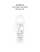
DT-3369T-BT AC/DC TRMS CLAMP METER With Mobile APP
Safety International Safety Symbols This symbol, adjacent to another symbol or terminal, indicates the user must refer to the manual for further information. This symbol, adjacent to a terminal, indicates that, under normal use, hazardous voltages may be present Double insulation SAFETY NOTES • Do not exceed the maximum allowable input range of any function. • Do not apply voltage to meter when resistance function is selected. • Set the function switch OFF when the meter is not in use.
CAUTIONS • Improper use of this meter can cause damage, shock, injury or death. Read and understand this user manual before operating the meter. • Always remove the test leads before replacing the battery or fuses. • Inspect the condition of the test leads and the meter itself for any damage before operating the meter. Repair or replace any damage before use. • Use great care when making measurements if the voltages are greater than 25VAC rms or 35VDC. These voltages are considered a shock hazard.
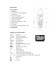
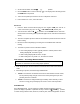
Description Meter Description 1. NCV Test 2. Current clamp 3. Non-contact AC voltage indicator light 4. Clamp trigger 5. Rotary Function switch 6. Data Hold and Backlight button 7. PEAK and INRUSH button 8. REL and HZ% button 9. MODE select and Bluetooth button 10. Max/Min button 11. LCD display 12. V Ω Diode Continuity CAP TEMP Hz% jack 13. COM input jack 14.
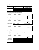
Specifications Function Range AC True RMS 60.00 Current 600.0A (Auto Rang) 1000A Resolution Accuracy (% of reading + digits) 10 mA +2.5% of rdg + 8 digits 100mA +2.5% of rdg + 8 digits 1A +2.8% of rdg + 8 digits Over rang protection: Maximum input 1000A Accuracy specified from 5% to 100% of the measuring range Frequency Response: 50Hz to 60Hz True RMS Function DC Current (Auto Rang) Range 60.00A Resolution 10mA Accuracy (% of reading + digits) +2.5% of rdg + 8 digits 600.0A 100mA +2.
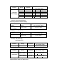
Function Capacitance (Auto-ranging) Range Resolution Accuracy (% of reading + digits) 60.00nF 10pF +5% of rdg + 30digits 600.0nF 0.1nF +3% of rdg + 5digits 6.000uF 1nF +3% of rdg + 5digits 60.00uF 10nF +3% of rdg + 5digits 600.0uF 0.1uF +4% of rdg + 10digits 6000uF 10uF +4.5% of rdg + 10digits Input Protection: 300V dc or 300V ac rms.
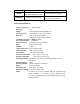
Function Testing Condition Diode Forward DCA is approx.1mA, open circuit Voltage MAX . 3V Continuity Test current MAX. 1.5mA Reading Forward voltage drop of Diode Buzzer makes a long sound, While resistance is less than(50Ω) Input Protection: 300V dc or 300V ac rms. General Specifications Clamp jaw opening Blue tooth Display Continuity check Diode test 1.2" (30mm) approx. 4.0 3-6/7 digits (6000 counts) backlit LCD Threshold 50Ω; Test current < 0.5mA Test current of 0.
Operation NOTES: Read and understand all Warning and Caution statements in this operation manual prior to using this meter. Set the function select switch to the OFF position when the meter is not in use. AC/DC Current Measurements WARNING: Ensure that the test leads are disconnected from the meter before making current clamp measurements. 1. Set the Function switch to the 1000A, 600A range. If the approx.
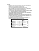
measuring. 1. Set the function switch to the CAP position. 2. Insert the black test lead banana plug into the negative COM jack and the re d test lead banana plug into the V· ·CAP·TEMP·Hz%·Ω Ω positive jack. 3. Touch the test probe tips across the part under test. If “OL” appears in the d isplay, remove and discharge the component. 4. Read the capacitance value in the display. 5. The display will indicate the proper decimal point and value.
2. Set the function switch to the Ω •))). position. 3. Use the MODE button to select continuity “••)))”. The display icons will change when the MODE button is pressed. 4. Touch the test probe tips across the circuit or component under test. 5. If the resistance is < 50Ω, a tone will sound. Diode Test 1. Insert the black test lead banana plug into the negative COM jack and the re d test lead banana plug into the V· ·CAP·TEMP·Hz%·Ω Ω positive jack 2. Turn the function switch to Ω •))). position.
between oF or oC. and in current position to select between AC or DC current measurements. To press and hold the mode key to turn the system on, the auto power off function will be cancelled. Press the Mode/Bluetooth until the Bluetooth turns on or off. PEAK/ INRUSH NOTE: Only ACV functions can do the peak value measurement. PEAK Key is the peak value measurement key that acts with trigger. NOTE: Only ACA functions can do the INRUSH value measurement. 1.
The LCD is equipped with backlighting for easier viewing, especially in dimly lit areas. Press the backlight button to turn the backlight on. Press again to turn the backlight off. Note that the meter does have an auto power off feature as described below. Automatic Power OFF In order to conserve battery life, the meter will automatically turn off after approximately 15 minutes. To turn the meter on again, turn the function switch to the OFF position and then to the desired function position.