
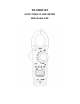
User's Manual


2. Set the function switch to the Ω
ΩΩ
Ω
•))).
position.
3. Use the MODE button to select continuity “•
••
•)))”. The display icons will change when
the MODE button is pressed.
4. Touch the test probe tips across the circuit or component under test.
5. If the resistance is < 50Ω, a tone will sound.
Diode Test
1. Insert the black test lead banana plug into the negative COM jack and the re
d test lead banana plug into the V· ·CAP·TEMP·Hz
%·Ω
ΩΩ
Ω positive jack
2. Turn the function switch to Ω
ΩΩ
Ω
•))). position. Use the MODE button to select the
diode function if necessary (diode symbol will appear on the LCD when in Diode test
mode)
3. Touch the test probe tips to the diode or semiconductor junction under test. Note the
meter reading
4. Reverse the test lead polarity by reversing the red and black leads. Note this
reading
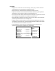
5. The diode or junction can be evaluated as follows:
If one reading displays a value (typically 0.400V to 0.900V) and the other
reading displays OL, the diode is good.
If both readings display OL the device is open.
If both readings are very small or ‘0’, the device is shorted.
Non-Contact AC Voltage Measurements
1. Touch the probe tip to the hot conductor or insert into the hot side of the electrical
outlet.
2. If AC voltage is present, the detector light will illuminate.
1. NOTE: The conductors in electrical cord sets are often twisted. For best results,
rub the probe tip along a length of the cord to assure placing the tip in close
proximity to the live conductor.
2. NOTE: The detector is designed with high sensitivity. Static electricity or other
sources of energy may randomly trip the sensor. This is normal operation
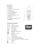
Mode/Bluetooth
Press Mode/Bluetooth key the selection of double measured functions which are
present at display is possible. In particular this key is active in V· ·CAP·
Ω
ΩΩ
Ω•))) position
to select among resistance test, diode test, continuity test, and in Temp position to select
WARNING
:
Risk of Electrocution. Before use, always test the Voltage
Detector on a known live circuit to
verify
proper operation