
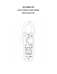
User's Manual


Operation
NOTES: Read and understand all Warning and Caution statements in this operation
manual prior to using this meter. Set the function select switch to the OFF position
when the meter is not in use.
AC/DC Current Measurements
WARNING: Ensure that the test leads are disconnected from the meter before making
current clamp measurements.
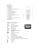
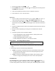
1. Set the Function switch to the 1000A, 600A range. If the approx. range of the
measurement is not known, select the highest range then move to the lower ranges
if necessary.
2. Press the REL button to zero the meter display.
3. Use the MODE button to select AC or DC Current.
4. Press the trigger to open jaw. Fully enclose only one conductor. For optimum results,
center the conductor in the jaw.
5. The clamp meter LCD will display the reading.
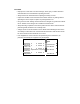
AC Voltage Measurement
1. Insert the black test lead into the negative COM terminal and the red test lead into
the positive V· ·CAP·TEMP·Hz
%·Ω
ΩΩ
Ω terminal.
2. Set the function switch to the V~ position.
3. Connect the test leads in parallel to the circuit under test.
4. Read the voltage measurement on the LCD display.
DC Voltage Measurement
1. Insert the black test lead into the negative COM terminal and the red test lead into
the positive V· ·CAP·TEMP·Hz
%·Ω
ΩΩ
Ω terminal.
2. Set the function switch to the V- position.
3. Connect the test leads in parallel to the circuit under test.
4. Read the voltage measurement on the LCD display.
Resistance
1. Insert the black test lead into the negative COM terminal and the red test lead into
the V· ·CAP·TEMP·Hz
%·Ω
ΩΩ
Ω positive terminal.
2. Set the function switch to the Ω
ΩΩ
Ω
•))).
position.
3. Touch the test probe tips across the circuit or component under test.
4. Read the resistance on the LCD display.
Capacitance Measurements
WARNING: To avoid electric shock, discharge the capacitor under test before