
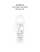
User's Manual


measuring.
1. Set the function switch to the
CAP position.
2. Insert the black test lead banana plug into the negative COM jack and the re
d test lead banana plug into the V· ·CAP·TEMP·Hz
%·Ω
ΩΩ
Ω positive jack.
3. Touch the test probe tips across the part under test. If “OL” appears in the d
isplay, remove and discharge the component.
4. Read the capacitance value in the display.
5. The display will indicate the proper decimal point and value.
Note: For very large values of capacitance measurement it can take several minutes
before the final reading stabilizes.
Frequency Measurements
1. Insert the black test lead banana plug into the negative COM jack and the re
d test lead banana plug into the V· ·CAP·TEMP·Hz
%·Ω
ΩΩ
Ω positive jack.
2. Set the function switch to the V~ Position.
3. Press HZ/% button to select the Frequency (Hz) or Duty cycle (%).
4. Touch the test probe tips across the part under test.
5. Read the value on the display.
6. The display will indicate the proper decimal point and value.
7. In Voltage and Current mode Press HZ/% button to select he Frequency (Hz)
or Duty cycle (%) .
Temperature Measurements
1. Set the function switch to the TEMP position.
2. Insert the Temperature Probe into the negative COM and the
V ·
·CAP·TEMP·Hz%·Ω
ΩΩ
Ω positive jacks, observing polarity.
3. Touch the Temperature Probe head to the device under test. Continue to touch the
part under test with the probe until the reading stabilizes.
4. Read the temperature on the display. The digital reading will indicate the proper
decimal point and value.
5. Use the MODE button to select
o
F or
o
C.
WARNING: To avoid electric shock, be sure the thermocouple probe has been removed
before changing to another measurement function.
Continuity Measurements
1. Insert the black test lead into the negative COM terminal and the red test lead into
the V· ·CAP·TEMP·Hz
%·Ω
ΩΩ
Ω positive terminal.