
Specifications


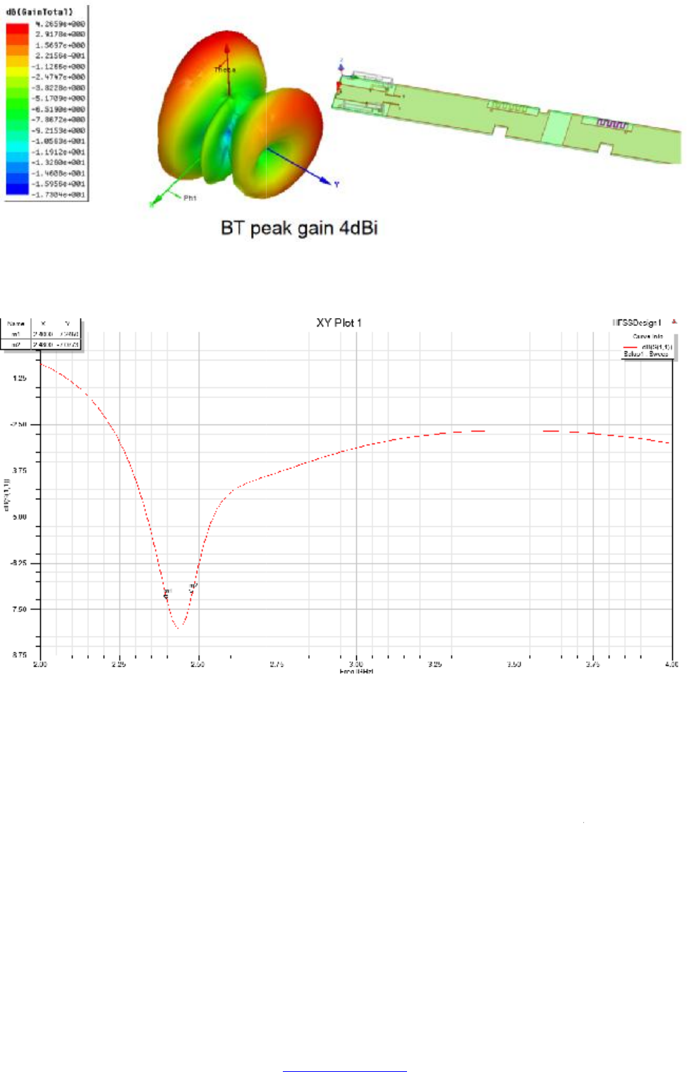
Figure 5 3D radiation pattern of
Figure 6
Structural design
The material that around the module should be plastic. In order to get stable high rate wireless connectivity
keep the module away from metal and metallic components as far as possible especially around the antenna,
antenna far away from metal at least 15c
m is suggested.
Recommend PCB Layout Footprint
Please use 10 PIN 1.25 GH connector.
Figure 5 3D radiation pattern of
PCB printed antenna
Figure 6
PCB printed antenna return loss
The material that around the module should be plastic. In order to get stable high rate wireless connectivity
keep the module away from metal and metallic components as far as possible especially around the antenna,
m is suggested.
Recommend PCB Layout Footprint
Please use 10 PIN 1.25 GH connector.
The material that around the module should be plastic. In order to get stable high rate wireless connectivity
keep the module away from metal and metallic components as far as possible especially around the antenna,
PDF pdfFactory Pro www.fineprint.cn