CONTENTS 1. TheRepeaterSystem.......................................................................................1 2. PackageContents...........................................................................................2 3. Installation........................................................................................................3 3.1. InstallationLocationRequirement...........................................................13 3.2. Installation ofOutdoorAntenna.............................
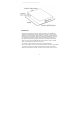
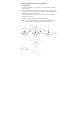
Introduction: The booster is designed to realize the wireless forwarding and bidirectional amplifying of the base station’s signal, expand the coverage of communication signal and cover its blind zone.
1.SignalBooster 2.IndoorAntenna 3.OutdoorAntenna 4.50 feet CoaxialCable 5.PowerAdapter 6.UserManual 7.Screws Accessories You should receive the Mobile Booster kit which includes the similar above-mentioned fittings.Before installing, please confirm your purchased booster’s frequency is corresponding with your cell phone frequency; if not corresponding, the booster would not amplify any signal.
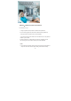
Step 1: Connect Inside Antenna To Booster Option A:Mount the Whip Antenna Installation Steps: 1.Connect the whip antenna to the Booster INDOOR port. 2.Gently rotate the whip antenna, place Inside Antenna in weak signal area. Note: 1. The whip antenna is suitable to be installed in small room or apartment. 2.The whip antenna should be oriented vertically whether you choose to mount the booster on a wall or set on a table.
Option B:Mount the Indoor Ceiling Antenna Installation Steps: 1. Drill a 20mm diameter hole in the ceiling. The ceiling thickness should be 30mm maximum. 2. Unscrew fixing nut from the antenna. Place antenna cable through the hole. Screw the fixing nut back onto the antenna, and go through the cable from the crawl space side of the ceiling and fasten. 3. Attach the connection from the indoor antenna to the connector labeled INDOOR on your booster. 4.
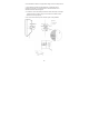
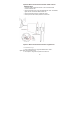
Option C:Mount the Indoor Panel Antenna Installation Steps: 1. Using the plate mark the position of desired screw placement. 2. Screw mounting plate into place with the slide protruding towards up. 3. Hang the antenna securely onto the mounting plate. 4. Connect the antenna short cable to the 15ft cable and run to the planned location of your booster. . 5. Place the booster on a flat surface or mounted to a wall and connect the remaining end of the cable to booster port marked INDOOR. Note: 1.
2.The installation location is the approximate height of normal cell phone use. 3. The Inside Panel Antenna is directional with a 180-degree reach, it should be mounted on a vertical surface or wall where there are no materials that could obstruct signals. 4. It is better to use a directional panel antenna when the shape of coverage is longand narrow (corridors, long row of houses in tow sides, tunnels, elevators or rural open space). 5. Do not connect booster to power until the system is fully installed.
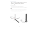
Step 2 : Install the Outdoor Antenna The directional Yagi, Panel or LPDA Antenna should be mounted at the highest possible location above the roof line ‒ at least 25 feet above the indoor antenna ‒ aimed in the direction of your nearest carrier’s cell tower. To find the location of your closest carrier’s cell tower, go to www.antennasearch.com. Ensure that the mounting area has at least a 12 inches radius clear of obstructions, other radiating elements and metal objects such as pipes or metal siding.
Option B: Mount the Directional Outdoor LPDA Antenna Installation steps: 1. A drill hole at the LPDA antenna bottom , and the drill hole should be face the bottom side. 2. Fix the LPDA antenna on a long pole/mast/tube with U-bolt and Brackets, tighten the the L-bracket with each washers nuts . 3. Fix the LPDA antenna at the L-bracket with screws 4. Let the peak of LPDA antenna pointed to the cell tower . Option C: Mount the Directional Outdoor YagiAntenna Installation Steps: 1.
Option D:Mount the Omni-directional Antenna Installation Steps: 1.Assemble the u-bolt, bracket, nuts and washers onto a mast (not provided) as shown in the illustration. 2.Connect one end of the provided coax cable to the antenna and tighten the connection. Note: 1.The Omni Antenna receives and sends signals in a 360-degree radius. Mount the antenna at the highest possible elevation and in an upright position. 2.
Step 3: Route & Connect Cable To System Connect the white 50ft Coaxial Cable to the Outdoor Antenna and route cable into the home.
Note: The connector need to add waterproof tape Step 4: Power Up The Booster & OptimizeThe System 11
12
Plug the Power Supply into wall outlet then connect to Booster.The minimum distance between outdoor antenna and indoor antenna shall be more than 39ft, again. Therepeatersshouldbeusedtocovertheindoorarea.Humidityandtemperatureofworking environmentcanaffectthereliabilityofrepeater.so,temperature,humidity,dust,interference,p ower,spacerequirementsandotherfactorsshouldbeconsideredduringinstallationof repeater. 3.
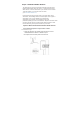
3.2 Installation of Outdoorantenna The repeater’s main function is improve weak RF signals of an area. A simple formula: Input power+ Gain=output power. The signal strength from the outdoor antenna directly affects the efficiency of the indoor coverage. it is very important to choose the outdoor antenna location in order to get the best signals.
Selecting the installation direction of outdoor antenna. The outdoor antenna should point in the direction of the tower, and it is much better to keep line of sight. Select opposite directions for outdoor antenna and indoor antennas. Please test the signal quality and make sure to avoid self-oscillation first, if have to install Outdoor and Indoor antennas in the same direction. If the directional antenna is selected, the main directional angle should point to the tower antenna.
3.3 Cable layout and connector assembly Connect cables to the booster’s ports after installing and fixing outside and inside antennas.Steps as below: (1)Open the cable package and make it bend naturally and smoothly. (2) Keep horizontal cables straight and fasten them with a fixing clip every 1 to 1.5 meters. (3)The cable should be bent naturally and smoothly to avoid cable damage caused by strong pulling.
3.4.Switch on the power After power is on, first check the alarm and power LEDS. Statu s Definition Gree n Normal Off DC power problem The status and definition of POWER indicators: 3.5. Check Coverage (1) PerformatestwithamobilephoneordatacardCheckbelow: - A weak input signal leads to the low output power. Need to change the direction of outdoor antenna or its installation position or replace outdoor antenna with higher gain antenna to increase input signal powerlevel.
(2) If the signals in small part of the areas have not been improved,please check below: - Check whether the service antenna is installed correctly or not, you may need to move the antenna location to improvecoverage. - Checkifitisnecessarytoadjustthedirectionoftheserviceantenna. -Check whether it is necessary to add one or more antennas to enhance the coverage of special areas.
1. The signal booster will only work with the correct frequency, so please make sure yourphonesignaliswiththesamefrequencyasthesignalbooster. 2. This cell phone signal booster will only make a weak signal stronger, it can't create a signal. That means it won't work if the outdoor antenna can't receive any signal. 3. The outdoor antenna should receive 2-3 bars of stable signal in the location where the outdoor antenna is fixed; otherwise, the booster won't work very well. 4.
The Solution to different LED Lights’ Status * Connecting indoor and outdoor antennas and then power on, the signal boosterandpoweradaptercanworknormallyiftheLEDofboostersta yon greenandadapter’sLEDalsokeepongreenorred. * Ifthebooster’sLEDareflashingingreenorred, oritsredindicatorlightst ay onwithoutconnectinganyantenna,meaningthat theboosterbreakdow nand pleasecontacttheCustomerServicetodothereplacement.
Remark: Increase the output power*---Recommended ways: adjust the outdoor antenna direction/location, or replace with a higher gain antenna to increase input signal strength. You should receive the Mobile Booster kit which includes the similar abovementioned fittings. Before using it, please confirm that your Booster’s frequency range is the same as your service provider’s network, otherwise, the amplifier will not work properly. Q1: Red Light on Booster Means the Self-oscillating Alarm. - A.
Q4: After finishing the installation, cell phone signal is improved but can’t make a call. - A.Verify outside antenna is mounted correctly. - B.Verify the location mounting outside antenna has stable signal,and confirm the direction of outside antenna is pointed towards to the cell tower. - C. Verify whether the local operator’s communication frequency is consistent with booster’s frequency. Q5: Phone calls and Internet access are in poor quality. - A.
TheFederalCommunicationsCommission(FCC)hastestedthisproductan dfound ittocomplywiththeirRFExposureRequirements,pursuanttoFCCPart22an d24. Don’t expose this product to extreme low or high temperature ( -20℃ and 55℃ ). Thereareonconsumerserviceableormodifiablepartsinsidethisboosterpro duct. Alteration or abuse of the booster or other components will void this product’s warranty, and could be dangerous to theuser. Do not purchase antennas, cables and couplers that are not authorized by FCC agencies.
30-day money-back guarantee, 3-month free replacement, 2-year manufacturer warranty Our Signal Boosters are warranted for 2 years against defects in workmanship or materials. Warranty cases may be resolved by returning the product directly to the manufacturer at the consumer’s expense, with a dated proof of purchase and an Order Number supplied. We shall either repair or replace the product at its option.
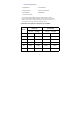
Complete list of authorized antennas, cables, and cable loss: Outdoor: Option 1: Yagi antenna with 15m 4D-FB cable to the Out Door port. Frequency(MHz) 698-716 728-746 Gain(dBi) 6 6 Cable Loss(dB) 3.5 3.6 Photo Remark Default Matching Antenna Option 2: Log periodic antenna with 15m 4D-FB cable to the Out Door port. Frequency(MHz) 698-716 728-746 Gain(dBi) 8 8 Cable Loss(dB) 3.5 3.6 Photo Option 3: Tubular antenna with 15m 4D-FB cable to the Out Door port.
Photo Option 4: Plate antenna with 15m 4D-FB cable to the Out Door port. Frequency(MHz) 698-716 728-746 Gain(dBi) 6 6 Cable Loss(dB) 3.5 3.6 Photo Indoor: Option 1: Equipment "INDOOR" ports with right Angle antenna. Frequency(MHz) 698-716 728-746 Gain(dBi) 2 2 Cable Loss(dB) * * Photo Remark Default Matching Antenna Option 2: INDOOR ports for suction dish antennas.
Gain(dBi) Cable Loss(dB) 3.5 * 4 * Photo Option 3: Omnidirectional roof suction antenna with 5 m 4D-FB cable and 'INDOOR' ports. Frequency(MHz) 698-716 728-746 Gain(dBi) 1.5 2 Cable Loss(dB) 1.2 1.2 Photo Option 4: Panel antenna with 5 m 4D-FB cable and 'INDOOR' ports. Frequency(MHz) 698-716 728-746 Gain(dBi) 6 6 Cable Loss(dB) 1.2 1.2 Photo Warning:Unauthorized antennas, ,cables and/or coupling devices are prohibited by FCC rules.