GOODOCOM Technologies Confidential GOC-BA440 Specification GOC- BA440 Bluetooth+WIFI Module Specification Document Type: Bluetooth+WIFI Module Specification Document Number: GOC-BA440 Document Version: V2.3 Release 2019/08/20 Date: Mobile:15817435207 Bill Fax:0755-29658104 TEL:0755-29663177 Website:www.goodocom.
GOODOCOM Technologies Confidential GOC-BA440 Specification Copyright 2006~2019 by GOODOCCOM Technologies SHENZHEN INC., All Right Reserved NOTES: 1.The module must use ladder steel net, and recommend ladder steel net thickness 0.16—0.20mm. The adaptability of the products is adjusted accordingly. 2.Before the use of the module, bake at 60 degrees centigrade and bake for 12 hours. Release Record Version Number V1.0 V1.1 V1.2 V1.3 V1.4 V1.5 V1.6 V1.7 V1.8 V1.9 V2.0 V2.1 V2.2 V2.
GOODOCOM Technologies Confidential GOC-BA440 Specification Contents 1. Introduction ............................................................................................................................................ 4 2. Block Diagram ........................................................................................................................................ 4 3. Features ..................................................................................................................
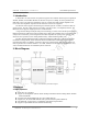
GOODOCOM Technologies Confidential GOC-BA440 Specification 1. Introduction In IEEE 802.11ac mode, the WLAN operation supports rates of MCS0–MCS9 (up to 256 QAM) in 20 MHz, 40 MHz, and 80 MHz channels for data rates of up to 433.3 Mbps. All rates specified in the IEEE 802.11a/b/g/n are supported. Included on-chip are 2.4 GHz and 5 GHz transmit amplifiers and receive low-noise amplifiers. Optional external PAs and LNAs are also supported.
GOODOCOM Technologies Confidential GOC-BA440 Specification TX and RX low-density parity check (LDPC) support for improved range and power efficiency. On-chip power amplifiers and low-noise amplifiers for both bands. Support for optional front-end modules (FEM) with external PAs and LNAs. Supports optional integrated T/R switch for 2.4 GHz band. Supports RF front-end architecture with a single dual-band antenna shared between Bluetooth and WLAN for lowest system cost.
GOODOCOM Technologies Confidential GOC-BA440 Specification High-speed HCI UART transport support with low-power out-of-band BT_DEV_WAKE and BT_HOST_WAKE signaling (see Host Controller Power Management) Channel quality driven data rate and packet type selection Standard Bluetooth test modes Extended radio and production test mode features Full support for power savings modes Bluetooth clock request Bluetooth standard sniff Deep-sleep modes and software regulator shutdown Supports a low-p
GOODOCOM Technologies Confidential GOC-BA440 Specification GOC-BA440 is qualified for and supports the mandatory features of the Bluetooth 5.0 specification. 3.3Standards Compliance TheGOC-BA440 supports the following standards: Bluetooth 2.1 + EDR Bluetooth 3.0 Bluetooth 4.2 (Bluetooth Low Energy) Bluetooth 5.0 compliant IEEE 802.11ac single-stream mandatory and optional requirements for 20, 40, and 80 MHz channels IEEE 802.11n (Handheld Device Class, Section 11) IEEE 802.11a IEEE 802.
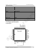
GOODOCOM Technologies Confidential Bluetooth Standard Frequency Band Interface WIFI Frequency Band Interface Size Operating Temperature Storage Temperature VBAT VDD_PIO Standby current Working current Max current Humidity GOC-BA440 Specification Bluetooth V5.0+2.1+BLE 2402MHz~2480MHz UART/PCM/I2S 2.4GHz/5GHz SDIO2.0/SDIO3.0 17mm*17mm*2.0mm -30℃~+85℃ -40℃~+125℃ 3.3V 1.8V~3.3V 25mA 350mA <700mA Operating Humidity 60% to 85% Non-Condensing Table 1: Specifications 5. Pin Diagram and Description 5.
GOODOCOM Technologies Confidential GOC-BA440 Specification 5.2 Pin Description Pin Pin Name Type Description 1 NC NC NC 2 GND Ground Ground 3 GND Ground Ground 4 IRQ_WL - SDIO available, interrupt out.
GOODOCOM Technologies Confidential GOC-BA440 Specification 32 NC NC NC 33 GND Ground Ground 34 VDD_PIO POWER 1.8V~3.3VSupply Voltage 35 VDD_PIO POWER 1.8V~3.
GOODOCOM Technologies Confidential GOC-BA440 Specification 5.3 PCB Layout Footprint Figure3:PCB Layout Footprint 5.
GOODOCOM Technologies Confidential GOC-BA440 Specification 6. External LPO_CLK Signal Requirement Parameter Nominal input frequency Frequency accuracy Duty cycle Input signal amplitude Signal type Input impedancela Clock jitter LPO Clock 32.768 ±200 30–70 200–3300 Square wave or sine wave >100k <5 <10,000 Units kHz ppm % mV, p-p – Ω pF ppm a:When power is applied or switched off. Table 3: External LPO_CLK Signal Requirement 7.
GOODOCOM Technologies Confidential GOC-BA440 Specification 2)VBAT should not rise 10%–90% faster than 40 microseconds. VBAT should be up before or at the same time as VDDIO. VDDIO should NOT be present first or be held high before VBAT is high. 8.2 Power on sequence for WLAN ON and BT ON Figure 6: WLAN = ON, Bluetooth = ON Notes: 1. VBAT should not rise 10%–90% faster than 40 microseconds. 2. VBAT should be up before or at the same time as VDDIO.
GOODOCOM Technologies Confidential GOC-BA440 Specification Notes: 1. VBAT should not rise 10%–90% faster than 40 microseconds. 2. VBAT should be up before or at the same time as VDDIO. VDDIO should NOT be present first or be held high before VBAT is high. 8.5 Power On Sequence for WLAN OFF and BT On Figure 9: WLAN = OFF, Bluetooth = ON Notes: 1. VBAT should not rise 10%–90% faster than 40 microseconds. 2. VBAT should be up before or at the same time as VDDIO.
GOODOCOM Technologies Confidential GOC-BA440 Specification Desired Rate 4000000 3692000 3000000 2000000 1500000 1444444 921600 460800 230400 115200 57600 38400 28800 19200 14400 9600 Actual Rate 4000000 3692308 3000000 2000000 1500000 1454544 923077 461538 230796 115385 57692 38400 28846 19200 14423 9600 Error (%) 0.00 0.01 0.00 0.00 0.00 0.70 0.16 0.16 0.17 0.16 0.16 0.00 0.16 0.00 0.16 0.00 Table4: Example of Common Baud Rates 10.
GOODOCOM Technologies Confidential GOC-BA440 Specification 10.1 Signal Connections to SDIO Host CLK CMD SD Host GOC-BA440 DATA[3:0] Figure 10: Signal Connections to SDIO Host 10.
GOODOCOM Technologies Confidential GOC-BA440 Specification 10.3 SDIO High Speed Mode Timing Diagram 10.
GOODOCOM Technologies Confidential GOC-BA440 Specification Card Input timing (SDR Modes) GOODOCOM Technologies Confidential 18
GOODOCOM Technologies Confidential GOC-BA440 Specification Card output timing (SDR Modes up to 100MHz) Card output timing (SDR Modes 100MHz to 208MHz) GOODOCOM Technologies Confidential 19
GOODOCOM Technologies Confidential GOC-BA440 Specification ∆tOP Consideration for Variable Data Window (SDR 104 Mode) 10.
GOODOCOM Technologies Confidential GOC-BA440 Specification 11. PCM Interface The PCM Interface on the GOC-BA440 can connect to linear PCM Codec devices in master or slave mode. In master mode,the GOC-BA440 generates the PCM_CLK and PCM_SYNC signals, and in slave mode, these signals are provided by another master on the PCM interface and are inputs to the GOC-BA440. The configuration of the PCM interface may be adjusted by the host through the use of vendor-specific HCI commands.
GOODOCOM Technologies Confidential GOC-BA440 Specification PCM Interface Timing Short Frame Sync, Master Mode Figure 11: PCM Timing Diagram (Short Frame Sync, Master Mode) Reference 1 2 3 4 5 6 7 8 Characteristics PCM bit clock frequency PCM bit clock LOW PCM bit clock HIGH PCM_SYNC delay PCM_OUT delay PCM_IN setup PCM_IN hold Delay from rising edge of PCM_BCLK during last bit period to PCM_OUT becoming high impedance Minimum 41 41 0 0 8 8 0 Typical - Maximum 12 25 25 25 Unit MHz ns ns ns ns ns ns
GOODOCOM Technologies Confidential Reference 1 2 3 4 5 6 7 8 9 Characteristics PCM bit clock frequency PCM bit clock LOW PCM bit clock HIGH PCM_SYNC setup PCM_SYNC hold PCM_OUT delay PCM_IN setup PCM_IN hold Delay from rising edge of PCM_BCLK during last bit period to PCM_OUT becoming high impedance GOC-BA440 Specification Minimum 41 41 8 8 0 8 8 0 Typical - Maximum 12 25 25 Unit MHz ns ns ns ns ns ns ns ns Table 5: PCM Interface Timing Specifications (Short Frame Sync, Slave Mode) Long Frame Sync
GOODOCOM Technologies Confidential GOC-BA440 Specification Figure 14: PCM Timing Diagram (Long Frame Sync, Slave Mode) Reference 1 2 3 4 5 6 7 8 9 Characteristics PCM bit clock frequency PCM bit clock LOW PCM bit clock HIGH PCM_SYNC setup PCM_SYNC hold PCM_OUT delay PCM_IN setup PCM_IN hold Delay from rising edge of PCM_BCLK during last bit period to PCM_OUT becoming high impedance Minimum 41 41 8 8 0 8 8 0 Typical - Maximum 12 25 25 Unit MHz ns ns ns ns ns ns ns ns Table 7: PCM Interface Timing S
GOODOCOM Technologies Confidential Reference 1 2 3 4 5 6 7 8 GOC-BA440 Specification Characteristics PCM bit clock frequency PCM bit clock LOW PCM bit clock HIGH PCM_SYNC setup PCM_SYNC hold PCM_OUT delay PCM_IN setup PCM_IN hold Minimum 20.8 20.
GOODOCOM Technologies Confidential GOC-BA440 Specification 12.2 Recommended Operating Conditions Operating Conditions Operating Temperature Storage Temperature Min -30°C -40°C Typical / / Max +85°C +125°C *The module is functional across this range of voltages. However, optimal RF performance specified in the data sheet is guaranteed only for 3.2V
GOODOCOM Technologies Confidential GOC-BA440 Specification these lines drive 4 ~ 8mA. UART_RX UART_TX UART_CTS UART_RTS The route length of these signals be less than 15 cm and the line impedance be less than 50Ω. 14.3 PCM Lines Layout Guideline The following HCI line routing must obey the following rule to prevent overshoot/undershoot, as these lines drive 4 mA. PCM_SYNC PCM_CLK PCM_OUT PCM_IN The route length of these signals be less than 15 cm and the line impedance be less than 50Ω. 14.
GOODOCOM Technologies Confidential 72pcs module in one tray 2000pcs modules into one pack Modules One Box GOC-BA440 Specification 4000pcs Carton size:270mm*275mm*220mm Tray size:225mm*205mm*7mm 17.3 Storage Requirements 1)Temperature: 22~28°C; 2 )Humidity: <70%( RH); Vacuum packed and sealed in good condition to ensure 12 months of welding. 17.4 Humidity Sensitive Characteristic 1) MSL: 3 level 2) Once opened, SMT within 168 hours in the condition of temperature: 22~28°C and humidity<60%(RH).
Federal Communication Commission Statement (FCC, U.S.) This equipment has been tested and found to comply with the limits for a Class B digital device, pursuant to Part 15 of the FCC Rules. These limits are designed to provide reasonable protection against harmful interference in a residential installation. This equipment generates, uses and can radiate radio frequency energy and, if not installed and used in accordance with the instructions, may cause harmful interference to radio communications.
Information that must be placed in the end user manual: The OEM integrator has to be aware not to provide information to the end user regarding how to install or remove this RF module in the user's manual of the end product which integrates this module. The end user manual shall include all required regulatory information/warning as show in this manual.
Integration instructions for host product manufacturers according to KDB 996369 D03 OEM Manual v01 2.2 List of applicable FCC rules FCC Part 15 Subpart C 15.247 & 15.207 & 15.209 2.3 Specific operational use conditions The module is a module with WIFI 2.4G function and WiFi 5G function and BT function Operation Frequency: BT/BLE: 2402-2480MHz 2.4GWiFi:2412~2462MHz 5GWiFi: U-NII-1: 5150 MHz to 5250 MHz, U-NII-3: 5725 MHz to 5850 MHz Type: PCB Antenna Gain: 2.5dBi Max.
2.9 Information on test modes and additional testing requirements Operation Frequency: BT/BLE: 2402-2480MHz 2.4GWiFi:2412~2462MHz 5GWiFi: U-NII-1: 5150 MHz to 5250 MHz, U-NII-3: 5725 MHz to 5850 MHz Type: PCB Antenna Gain: 2.5dBi Max.
FCC STATEMENT : This device complies with Part 15 of the FCC Rules. Operation is subject to the following two conditions: (1) This device may not cause harmful interference, and (2) This device must accept any interference received, including interference that may cause undesired operation. Warning: Changes or modifications not expressly approved by the party responsible for compliance could void the user's authority to operate the equipment.