2.
CONTENTS 1. Foreword 1 2. Packing List 1 3. Structure 2 4. Installation 3 5. Specifications 11 6.
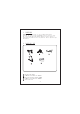
1. FOREWORD CONGRATULATIONS. The Wireless car rearview Camera, when used as described, will give you years of dependable service in your car, truck, RV, or mini-van. We have taken numerous measures in quality control to ensure that your product arrives in top condition, and will perform to your satisfaction. 2. PACKING LIST Car Rearview Camera 2.4GHz Wireless Receiver GT4013 Wireless Transmission Box Gt4065 2.
3.
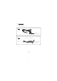
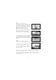
4. INSTALLATION These installation instructions do not apply to all vehicles. They are meant as only as a general guide due to common vehicle makes & models. For specific questions, contact your vehicle's manufacturer. Consult your local motor vehicle laws on the use of this product. 4-1 CAMERA INSTALLATION You may mount the camera near the license plate's top with screws. 1. Uplift the backside door of vehicle and remove the cover to install profitably. (Fig1) 2. Drill three holes.
Note: * Some vehicle's may have a hole available to pass the wire through, if not, you need to drill a hole close to the location of camera for the connector wire, and two holes for the screws of camera installation. * Before you drill those holes, you must check out and make sure no other components too close to your aiguille. Before drilling, we strongly commend you remove electrical parts or fuel system behind the vehicle door and clear the surroundings to avoid unexpected damages. 3.
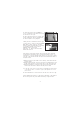
To locate the reverse light's 12/24VDC wire it will be necessary to gain access to the rear of the vehicle's tail light. For help locating the vehicle's reverse light circuit contact your vehicle's manufacturer for vehicle specific wiring diagrams. (Fig6) 7.Once you have located the reverse light circuit you will have to route the GT4062 Power Wire to that location. You must securely fasten the Power Wire to prevent it from being caught on any vehicle component such as the trunk hinge (Fig. 7).
10. Following the In-Line Wire Connector Instructions section, splice the Red wire using the supplied In-Line Wire Connector to the reverse light's positive(+) wire. Use a set of slip joint pliers to squeeze the TAP and insure good connection. 11. Next splice the black wire of the transmission box GT4062 power wire to the reverse light's negative(-) wire or ground. 12. Replace the reverse light bulb, then reinstall the light socket. Secure all the wire with cable ties or electrical tape.
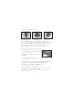
In-Line Wire Connector Instructions Insert the existing wire to be tapped. Insert the wire to be attached. Crimp tap then close lock You do not need to use the In-Line Wire Connectors. GT4062 can be wired directly to the reverse light circuit by stripping the reverse light wires then twisting GT4062 wires to the exposed reverse light wires. Once connected, wrap with electrical tape. Do not attempt this if you are not knowledgeable with electrical installation practices.
5. SPECIFICATIONS GL8902+GT4065 510 Horizontal View Angle +12V DC 150mA - (Max.) RECEIVERGT4013 586(PAL) ISM 2,400-2,483MHz 2mW/FCC,10wm/CE <0.5 Lux 4m Minimum Illumination IR Night Range RECEIVERGB4096 496(NTSC) 628 80 degree FM ISM 2,400-2,483MHz 12V/24V DC Modulation Input voltage Output current Output Voltage Received Sensitivity Consumption Current (Max.) 1.5A 5V ≤-85dBm 1.
FCC INFORMATION This device complies with part15 of the FCC Rules. Operation is subject to the following two conditions: (1) this device may not cause harmful interference, (2) this device must accept any interference received, including interference that may cause undesired operation. Changes or modifications not expressly approved by the party responsible for compliance could void the user’s authority to operate the equipment.
GOSPELL Smarthome Electronic CO.,LTD. 4-5Floor/Block 2, Vision (SZ) Park, Hi-Tech Industrial Park, Shenzhen, P.R.