
Operation Manual


6 / 8
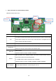
4. Product block diagram description
1、The network module is integrated in the display screen, and the power supply and power failure of the
module are provided by the internal power bus of the display screen.
2、 The wifi antenna of the network module is installed internally and integrated. The antenna uses IPEX
connection interface mode to ensure good contact.
Built in diagram of network module:
It is essential for module grantees to clearly and explicitly state the RF exposure conditions that permit a host
product manufacturer to use the module. Two types of instructions are required for RF exposure information: (1) to
the host product manufacturer, to define the application conditions (mobile, portable – xx cm from a person’s body);
and (2) additional text needed for the host product manufacturer to provide to end users in their end-product
manuals. If RF exposure statements and use conditions are not provided, then the host product manufacturer is
required to take responsibility of the module through a change in FCC ID (new application).