SAFETYTRAINING INFORMATION Your HYT radio generates RF electromagnetic energy during transmit mode. This radio is designed for and classified as “Occupational Use Only”, meaning it must be used only during the course of employment by individuals aware of the hazards, and the ways to minimize such hazards. This radio is NOT intended for use by the “General Population” in an uncontrolled environment. This radio has been tested and complies with the FCC RF exposure limits for “Occupational Use Only”.
ALWAYS keep the antenna at least 150 cm away from the body when transmitting The information listed above provides the user with the information needed to make him or her aware of RF exposure, and what to do to assure that this radio operates with the FCC RF exposure limits of this radio. Electromagnetic Interference/Compatibility During transmissions, your HYT radio generates RF energy that can possibly cause interference with other devices or systems.
OPERATING NOTES When transmitting, Please Keep the antenna at least 150 cm from your head and body. PRECAUTIONS WARNING! NEVER hold the transceiver so that the antenna is very close to, or touching exposed parts of the body, especially the face or eyes, while transmitting. The transceiver will perform best if the microphone is 150 cm away from the antenna. WARNING! NEVER operate the transceiver with a headset or other audio accessories at high volume levels.
Revision History P/N Release Date Revision Initial Release General Manual Scope This manual is intended for use by experienced technicians familiar with similar types of communication equipment. It contains all service information required for the equipment and is current as of the publication date. Safety and General Information The following general safety precautions as would normally apply, should be observed during all phases of operation, service and repair of this equipment.
TR-800 Service Manual ◇ Do not place the repeater in excessively dusty, humid areas, nor on unstable surfaces ◇ Connect to the lightning arrester prior to the antenna which is installed outdoors, and the chassis or equipment housing must be connected to an absolute earth ground, to minimize any possible shock hazard from lightning strike. ◇ Please make sure no stress on the antenna joint during transportation or installation.
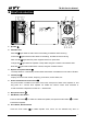
TR-800 Service Manual Brief Introduction 1 18 2 3 4 5 6 TX RX 19 7 BAT 8 20 9 10 RPT OPT MONI SCAN 11 12 UP DN 13 14 15 21 16 22 17 1. Speaker ① 26 25 24 23 2. LED Indicators Red LED ② lights while the main radio is transmitting, and flashes while receiving. Green LED ③ lights while the slave radio is transmitting, and flashes while receiving. Dark red LED ④ lights while DC power supplies and the AC power fails.
TR-800 Service Manual uni-directional mode (forward directional, i.e., RPT is active while OPT is inactive). 17 to display channel frequency by turns of slave radio Rx frequency, Short press the Monitor button○ slave radio Tx frequency, main radio Rx frequency, main radio Tx frequency; long press it to monitor the activities on the current channel. The main radio processes monitoring while OPT is active, the slave radio processes monitoring while OPT is inactive. 9.
TR-800 Service Manual Software Specification Basic Operation Short press the power switch to turn on the repeater; rotate the volume control knob clockwise to adjust the volume for a comfortable listening level. Press the “Up” or “Down” button to select a desired channel, then the repeater operates as you set. 1. To achieve the basic repeater functions, the radio must be in the repeater setup, and operates in the uni-directional or bi-directional repeater mode.
TR-800 Service Manual button to initiate repeater scan (if scan parameter is applicable). The Scan Interval Time and Dropout Delay Time are configurable via the programming software. Signalling Squelch This feature can be enabled/disabled by your dealer. If the feature is enabled, the preset DTMF/2-Tone /5-Tone will control repeater mute/unmute. The repeater will not unmute until valid signalling is received.
TR-800 Service Manual Repeater Modes -6-
TR-800 Service Manual Base Station Knockdown Mode Forward Directional Repeater Setup Mode Reverse Directional Repeater PC Programming Mode Bi-directional Repeater Modes Description Mode Description Knockdown Press the SETUP button while the repeater is power on. The repeater enters knockdown mode once the orange LED goes out. Base Station Press RPT and OPT buttons when the SETUP orange LED is on. The radio enters base station mode once both the RPT and OPT blue LEDs go out.
TR-800 Service Manual Press the SETUP button located on the front panel to toggle between repeater setup and knockdown, with LED indications. While in setup state, both radios turn on at power up; in knockdown state, only receive radio turns on at power up. There are three repeater types: base station, uni-directional and bi-directional in the repeater setup state. The repeater is initialized to base station mode when it toggles from knockdown to setup state.
TR-800 Service Manual Appears when the current channel is already in use Appears when the Monitor key is pressed to disable CTCSS/DCS, DTMF, 2-Tone/5-Tone decoding. Appears when the repeater is unmuted upon the monitor key is pressed. A Indicates the feature development feature. SCAN Appears while repeater scanning. CALL Appears when transmitting a selective call. Appears when a message is received.
TR-800 Service Manual OPT Blue, ultra bright SETUP Orange BAT Dark red 1. Lights while the OPT is active. 2. Goes out while the OPT is inactive. 1. Lights while in the Setup state. 2. Goes out while in the Knockdown state. 1. Lights while the backup battery supplies power. 2. Goes out while the AC mains supplies power.
TR-800 Service Manual Circuit Description Repeater Communication Interface & Display Unit Theory of Operation Setup/Knockdown (U0107D, Q0101, Q0103, Q0106, Q0107 and Q0108): The Setup/Knockdown state at power-up can be configured via HR-800 programming software. The electronic switch, Q0106 and Q0108, causes the Setup/Knockdown action by applying or removing voltage at the ignition control, pin15, of “J0102-Main”.
TR-800 Service Manual low state at the input of the NAND gate U0107A, one quarter of a MC14011B, will be conversed to a high state to drive the buffer for the Rx Carrier signal. The active low level of Rx Carrier signal, along with the OPT enable signal, cause a series of NAND gates, U0103D, U0103C and U0103B to generate a high dc level to turn on Q0102. The output of Q0102 is pulled low for pin8 of “J0104-Slave” and keys the transmitter of slave radio. The green “Rx” LED, CR0105, illuminates.
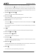
TR-800 Service Manual Figure Ⅰ Block Diagram -13-
TR-800 Service Manual Power Management Theory of Operation Battery Revert Circuit: A voltage reference network consisting of CR0212, CR0213, R0268, and VR0209 provides a stable voltage reference of 7.5Vdc. This reference voltage, at the anode of VR0209, is applied to the negative input of the Over Voltage Detector U0206B-6, to the positive input of AC Fail Detector U0206A-3, and to the positive input of the Low Battery Detector U0205B-5.
TR-800 Service Manual Variable speed, Temperature controlled Fan Circuit: The TL431AILP is a three-terminal programmable shunt regulator diode. This monolithic IC voltage reference operates as a low temperature coefficient zener that is programmed from 6Vdc to 12Vdc with a resistor network consisting of R0296, R0297 and an NTC thermistor Rth0201. Q0219 operates as a fast power switch between “ON” and “OFF” (similar to PWM mode) controlled by the output at cathode of TL431AILP.
TR-800 Service Manual Glossary Bi-directional Repeater: A repeater configuration in which the main and slave radios perform both receive and transmit functions. The audio and Rx Carrier signals from the receiver of the slave radio are routed to the transmitter of the main radio. Unlike the unidirectional case, though, the audio and Rx Carrier signals of the receiver of the main radio are also routed to the transmitter of the slave radio.
TR-800 Service Manual MPU Pins Repeater front panel (MPU Model: uPD780114, CRYSTAL: 9.8304MHz) PIN No.
TR-800 Service Manual 35 RPT/O O RPT signal output Active: H 36 KEYBL O Keypad backlight control 37 Rx Tone/I I Slave radio signal input Active: L () 38 SETUP/I I SETUP signal input On: H (rising edge trigger) 39 OPT/I I OPT key input Active: L 40 RPT/I I RPT key input Active: L 41 DN I DN key input Active: L 42 UP I UP key input Active: L () 43 SCAN I SCAN key input Active: L () 44 MONI I MONI key input connected) Active: H Active: L () () () (external p
TR-800 Service Manual TR-800 Part List (Logic board) No. 1 2 3 P/N Part Description Ref. No.
TR-800 Service Manual 4 3001061040010 Chip resistor 0603 100KΩ J 1/10W R1121 B2D R0118 B3F R0145 B1B R0198 B4E R1106 B2D 4 5 3001061220000 Chip resistor 0603 1.2KΩ J 1/10W R0125 B2E 1 6 3001061510000 Chip resistor 0603 150Ω J 1/10W R0168 B2A 1 7 3001061520000 Chip resistor 0603 1.
TR-800 Service Manual 16 3001065620010 Chip resistor 0603 5.6KΩ J 1/10W R0188 B3B R0189 B3B R0190 B3B R1105 B3B R1111 B4B R1112 B3B R0138 B2F R0157 B2C 2 17 3001065630000 Chip resistor 0603 56KΩ J 1/10W R1109 B2D 1 18 3001066800000 Chip resistor 0603 68Ω J 1/10W R0167 B3A 1 19 3001066820000 Chip resistor 0603 6.8KΩ J 1/10W R1104 B3B 1 20 3001066830000 Chip resistor 0603 68KΩ J 1/10W R1110 B3D 1 21 3001162290000 Chip resistor 2010 2.
TR-800 Service Manual 30 31 32 33 34 35 36 3101073340000 3101074710010 3104081060070 3104081560020 3213212102010 3221506601000 3301240700000 Chip capacitor 0805 0.
TR-800 Service Manual 39 40 3307110100090 3399010600000 LED KPT-1608CGCK Green Switching Diode HSB123TR-E VR0105 B4E VR0106 B2E VR0107 B2F CR0107 T4F CR0108 T3F CR0111 T4F CR0112 T2F CR0113 T2D CR0114 T3D D0112 B4B D0113 B4B D0114 B3B D0115 B4B D0116 B3B D0117 B4B D0118 B2B D0119 B3B 6 8 41 3403002000000 Transistor 2SB1132L02T100R Q0118 B4C 1 42 3403008000010 Transistor DTC114EE(TL) Q0102 B3E 9 Q0105 B2E Q0111 B2E Q0114 B2D Q0115 B3A Q0117 B2A
TR-800 Service Manual 52 3610003000000 SCM UPD78F0114HGB-8ES U0110 B3B 1 53 3701098340020 Crystal 9.8304MHz NX8045GB SMD X01 B3B 1 54 4002000000070 Fuse 0466.200.NR 0.2A/125V F0101 B5F 1 55 5202008100020 Chip socket 52746-0870 8pin J0110 T3A 1 56 5202011100010 Chip socket B11B-ZR-SM3-TF(LF) J0106 B1C 2 J0107 B5D 57 410R800100030 TR-800 Logic board PCB FR4 1.
TR-800 Service Manual TR-800 Part List 1 (Power Management Board) No. P/N 1 3001061000000 2 3001061020010 3 4 3001061030010 3001061040010 Part Description Ref. No. Address Qty. Chip resistor 0603 10Ω J 1/10W R2103 T2E 1 Chip resistor 0603 1KΩ J 1/10W R0285 T2B 2 R2101 T2D R0278 T2B R0284 T2A R0287 T3B R2100 T2B R0274 T1A R0281 T2A R0289 T3B Chip resistor 0603 10KΩ J 1/10W Chip resistor 0603 100KΩ J 1/10W 4 3 5 3001062720000 Chip resistor 0603 2.
TR-800 Service Manual 18 3101074710010 Chip capacitor 0805 470PF K 50V C0233 T2A C0240 T2D C0227 T2B C0228 T1B C0229 T2B C0231 T1A C0235 T2A C0236 T3A C0237 T3A C0238 T3A 8 19 3101081050020 Chip capacitor 1206 1UF K 25V C0242 T2D 1 20 3414001000040 Transistor 300MHz 0.
TR-800 Service Manual 32 3103991060020 Electrolytic capacitor 4*7 10UF ±20% 25V C0230 B2B 1 33 3103991070090 Electrolytic capacitor 6*12 100UF C0225 B2D 2 C0232 B2D ±20% 25V 34 3103992280020 Electrolytic capacitor 12.5*25 2200uF ±20% 25V C0241 B2D 1 35 3103994770030 Electrolytic capacitor 2512 470UF 25V M 105℃ C0243 B3E 1 36 3216599224000 Bobbin inductor 0.
TR-800 Service Manual Adjustment Description Logic Board Adjustment Test Apparatus 1. 2. 3. 4. 5. 20A/30V Power Supply 1set Ammeter 1set Digital Voltmeter 1set Test Jumper Cables (mating with test ports of TR-800 and the communication test set) Communication System Analyzer (such as HP8921 series) 1set Adjustment Radio Configuration Use HR-800E to program the TR-800. Table Ⅰ and table Ⅱ illustrate the factory default settings in a general operation mode.
TR-800 Service Manual tones to rated check power, receiver’s squelch open/off sensitivity, with signaling open squelch sensitivity, audio distortion & Squelch off sensitivity: -118±3dBm CCTSS squelch sensitivity: -118±3dBm CDCSS squelch sensitivity: -118±3dBm Audio distortion: ≤3%@3W ≤10%@5W Rx S/N Rx S/N: ≥45dB (wide) ≥40dB (narrow) Adjust the audio Main Any channel radio without transmit tones Main radio Communication Tx test set / connector MIC output amplitude of Analyzer
TR-800 Service Manual amplitude of the analyzer, check the ≤10%@5W Tx S/N: ≥42dB (wise) ≥37dB (narrow) duplex sensitivity. Max.
TR-800 Service Manual Long press the monitor key, Any MONI / channel / MONI the Check up main radio monitoring, with processes red LED flashes. Adjust the audio output amplitude of the analyzer MIC to 7mVinto 3 pin of Any Slave radio transmit channel Communication without test set J0109, check the Slave radio Rx TX frequency dev. / Matching of 60% connector tones system Dev., check duplex frequency deviation: 3.0±0.2kHz (wide) 1.5±0.
TR-800 Service Manual Item Condition Measure Instrument Adjustment Point Point Method Specification/Remark Short or long press of the monitor Knockdown state Any channel Handheld with SETUP microphone or disabled test cable and scan button is disabled; unable MONI, / SCAN pushbutton / to transmit with palm microphone or test cable connected, only receives (i.e.
TR-800 Service Manual Power Management Board Adjustment Test Apparatus 1、 20A/30V Power Supply 2、 Analog ammeter 3、 Digital Voltmeter 4、 12V lead acid battery (not fully charged) 1set 1set 1set 1set Circuit detect and temperature-control test Connect CN0201 (To Power Supply) and CN0204 (To Ext. Battery) with DC power output 13.8V respectively.
TR-800 Service Manual Floating charge test Connect CN0204 to 12V battery; CN0201 remains connected with 13.8V power supply. Item Floating charge Condition / Measure Instrument Analog Ammeter Adjustment Point Point Method Specification/Remark Check the charging current is about CN0204 / Check 400mA, and will drop to 10-25mA when fully charged.
TR-800 Service Manual Duplexer Instructions Electrically a duplexer is a device using sharply tuned resonate circuits to isolate a transmitter from a receiver. This allows both of them to operate on the same antenna at the same time without the transmitter RF frying the receiver.
TR-800 Service Manual 1. 2. 3. 4. 5. Adjust the frequency of the communication test set or generator to that of receive. Place the main radio on the receive frequency mode defined in Step 1 under “Programming the Radios”. Adjust the level of the communication test set or generator until the main radio emits a weak signal. Increase the level of the communication test set or generator by approximately 20dB. Adjust the tuning screw of the duplexer for the greatest rejection of the signal.
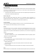
TR-800 Service Manual Disassembly and Installation Removing and Installing the Top Cover 1. using a screwdriver to Remove the seven screws (M3.0X6.0) ① that locking the top cover of repeater, shown as Figure 1. 2. Remove the top cover ②, shown as Figure 1. 3. Install the top cover as reverse steps. 1 1 1 2 1 1 1 1 Figure 1 Removing and Installing the Front Panel 1. Press the 6 latches that locking the front panel to the housing to separate and remove them from the housing ①, shown as Figure 2. 2.
TR-800 Service Manual Removing and Installing the Control Panel 1. Remove the Volume Control knob ① shown as Figure 3. 2. Remove the nut ② using a special spanner, shown as Figure 3. 3. Remove the six screws (ST3.0X8.0) ③ that secure the control panel using a screwdriver, shown as Figure 4. 4. Gently press and remove the RJ45 port ④ from the front panel, then pull out the speaker cable to remove the controller PCB, shown as Figure 4. 5. Install the control panel as reverse steps.
TR-800 Service Manual Figure 5 Removing and Installing the Radio 1. Remove the screw (M4.0X6.0) ① that secure the thermistor sensor using a screwdriver, shown as Figure 6. 2. Remove the eight screws (M3.0X6.0) ② that secure the bracket of radio using a screwdriver, shown as Figure 6. 3. Remove the bracket ③ shown as Figure 6, and remove the 2 signal cables and 2 power cables of both radios. 4. Remove the eight screws (M4.0X6.
TR-800 Service Manual 1 1 1 1 Figure 8 Removing and Installing Switch Power 1. Remove the four screws (M4.0X6.0) that secure the switch power using a screwdriver, to remove the switch power ①, shown as Figure 9. 2. Install the switch power as the reverse steps. 1 1 1 1 Figure 9 Removing and Installing the Power Management PCB 1. Remove the four screws (M3.0X6.0) that secure the power management PCB using a screwdriver, to remove the power management PCB ①, shown as Figure 10. 2.
TR-800 Service Manual Exploded View 27 28 29 30 G G G F G 31 B F B 32 H H H H 33 H F 34 35 F C F H 7 10 9 8 13 14 11 12 15 16 H 17 18 36 C C CC H C J 38 J F I 39 G 5 F D D F F A B C 19 49 50 51 F 20 21 25 44 45 48 F 23 43 B 47 F 2 40 41 42 46 CC 1 J F F F E BB 3 B I F 4 F F E D J I E D 6 I G E 37 F I 22 F 24 F F F 55 F 56 26 52 53 54 H H H 65 64 63 62 61 60 59 58 57 -41-