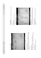
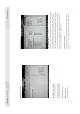
25 Fig 3.5 To select the address of PI (parallel interface). · Parallel Port Address If IR device (IrDA) is available, it is recommended it be set as IrDA ASKIR. If set as Normal, it is for the use of regular mouse and Modem. · Serial Port 1 Mode is “3F8 / IRQ4”. 3F8 / IRQ4, 2F8 / IRQ3, 3E8 / IRQ4, 2E8/ IRQ3 and Auto. The default value To set the built-in serial port 1 (COM1 port). The options are: D i s a b l e d 、 · Serial Port 1 Address (SI 1) 3.
7 any support. accordance with the later setup even if no operating system provides is selected, BIOS can set the system as power-saving mode in management) function. The default value is “Enabled”. When [enabled] This item is used for enabling or disabling the APM (advanced power · Power Management/APM Options are [disabled] and [enabled]. This item allows you decide whether acpi apic form to rsdt indication list. · ACPI APIC support To set the power type the system can support.
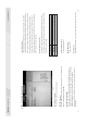
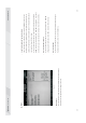
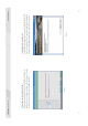
29 · Bootup Num-Lock (To set the state of Num Lock after start-up). Options are OFF and ON. · Add On ROM Display Mode [Force BIOS] This item allows you to set the display mode of the device's firmware program. The options are [Force BIOS] and [Keep Current]. · Quiet Boot To start the system quietly. Fig 3.8 · Quick Boot If this item is set as Enabled, the system can be started within five seconds and some detection items will be ignored. The options are [Disabled] and [Enabled]. 5.
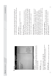
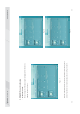
31 Fig 3.9 If this function is selected, the following information will appear: Enter New Password hhhhhh 6. Security Setup · CD/DVD Drives To set the booting priority of CD/DVD-ROM devices. · Removable Drives To set the booting priority of removable devices. · Hard Disk Drives To set the booting priority of hard disk devices. · Boot Device Priority To set the booting priority. screen and buzz. write information in the sector, BIOS will display alarm information on the IDE disk sector.
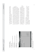
33 · USB Configuration To set the USB device. · RX780 Configuration · SouthBridge Configuration To set the south bridge chip. · NorthBridge Configuration To set the north bridge chip. 7. Setup for Chipset Fig 3.10 Fig 3.11 mode. The two options were HiSpeed (480 Mbps) and Full Speed (12 Mbps) This item is used for setting the transfer rate mode of USB 2.0 device. · USB2.0 Controller Mode The options are [Disabled], [Enabled] and [Auto].
35 Fig 3.12 value/discard changes/discard changes and exit. The exit options include load optimal defaults/load failsafe defaults · Exit Options 8. Exit If press Cancel or Esc, return to the main menu. If you enter OK and press Enter, the system will discard the changes. · Discard Changes setup program. If press Cancel or ESC, return to the main menu.
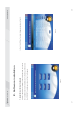
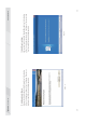
37 Fig. 4.1 the CD-ROM. The interface as shown in Fig. 4.1 will appear. then install the driver for the motherboard. To this end, put the disk into After you complete the installation of the operating system, you should 1. Install driver for motherboard IV. Software installation Fig. 4.2 In Fig 4.1, click "Driver ", another UI appears as shown in Fig 4.2.
39 of Fig. 4.2, a dialog box as shown in Fig. 4.4 will pop up. Then you can click “Next” and wait till the driver is installed completely. of Fig. 4.2, a dialog box as shown in Fig. 4.3 will pop up. Then you can click Next and wait till the driver is installed completely. Fig. 4.4 After you click “Install” behind the “Realtek HD audio driver” in the interface After you click “Install” behind the “Intel Chipset driver” in the interface Fig. 4.3 1.2 Install Sound card driver 1.1.
41 indications in the popped-up dialog boxes, and then restart the computer. can click “Next” and wait till the driver is installed completely. Fig. 4.6 Driver” in the interface of Fig. 4.2, complete the installation by following the Fig. 4.5 To install the driver for graphic card, you can click “Install” behind “H55 VGA After you click “Install” behind the “Realtek 10/100/1000 LAN Driver” in the 1.4 Installing driver for graphic card interface of Fig. 4.2, a dialog box as shown in Fig. 4.
43 is mute. You need to turn it on manually, as shown in Fig. 4.8 and 4.9. After the initial installation of the driver, the default state of microphone Fig. 4.7 installed, as shown in Fig. 4.7. The control panel of the audio adapter will appear after the driver is · For Windows XP SP2: 2. HD-AUDIO sound card setup Fig. 4.9 Fig. 4.
45 shown in Fig. 4.10 and 4.11. Fig. 4.10 Manager at the lower right corner. The initial interface will pop up, as After the driver for the audio adapter is stalled, you can click the Audio · For Windows Vista: Fig. 4.12 “separate all input jacks as independent input devices”. Device, the interface shown in Fig. 4.12 will pop up. Then select Click the right upper part of the control interfaceAdvanced Setup for Fig. 4.
47 volume for recording and the playing volume for the MIC. set the device as default. In the above interface, you can adjust the If a MIC is used, please select the corresponding front or rear mode and Fig. 4.13 Click OK, and the controlling interface will turn to one shown in Fig. 4.13. as shown in Fig. 4.14. Fig. 4.14 mouse at the corresponding output interface.
49 Fig. 4.15 Select Redistribution of Connectors. Then an interface will pop up, as shown in Fig. 4.15. After that, set the corresponding output. harmful interference, and ( 2) this device must accept any interference received, including interference that may cause undesired operation. (1) this device may not cause This device complies with Part 15 of the FCC Rules.