
User's Manual


11
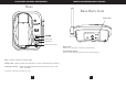
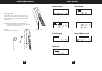
1. Connect the telephone line cord to the jack and to a
telephone outlet.
2. Connect the AC power adapter to the 9V DC jack and to an AC outlet.
3. Insert the pedestal into the slots on the bottom of the
base and slide up to lock in place. The pedestal is
reversible for desk or wall mounting.
4. Raise the antenna vertically.
: If your telephone outlet is not modular, contact your
telephone Company for assistance.
LINE
Tip
Note:
Note
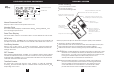
Use only the supplied AC power adapter. Do not
use any other AC power adapter. Connect the AC
power adapter to a continuous power supply. Place
the phone close to the AC outlet so that you can
plug in the AC power adapter easily.
: The handset can be placed either face up or face down in the
Base when desk mounted.
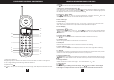
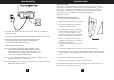
The GH2410 telephone may be installed onto two screws (not included)
fastened into the wall.When installing screws into plasterboard walls use wall
anchors (not included) to ensure that the screws remain secure. Insert the
screws into the wall leaving 3/16" of each screw extending out from the wall.
The Gh2410 is not compatible with mounting on a standard
telephone wall plate.
1. Remove the handset from the base.
2. Adjust the base to the wall mount position.
3. Place the pedestal to the wall mount
position and slide into place.
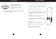
4. If mounting over a telephone wall jack,
plug the supplied short telephone cord
intothejacklabeledLINEonthe
telephone. Thread the line cord through
the slot on the backside of the phone.
5. If wall mounting with screws, plug the
supplied 7-foot telephone cord into the
LINE jack on the telephone.
6. Connect the telephone line cord to the
wall jack.
7. Insert the AC adapter into the 9V DC jack on the top of the base.
8. Slip the telephone base onto the wall, lining up the wall mounting holes over
the wall plate posts or screws. Slide the telephone base down so it is firmly in
place.
9. Return the handset to the telephone base.
10. Plug the other end of the AC adapter into the AC outlet.
Note: For safety when wall mounted, the handset should only be placed in the
base with the caller ID display facing out.
TELEPHONE SETUP TELEPHONE SETUP
12
Connecting the BaseConnecting the Base
Wall Mounting
T/P
TEL
-
+
POWER SOURCE 9VDC 300mA
USE ONLY WITH CLASS 2
Pedestal
Wall Mounting Instructions: