N901 Smart Helmet User Manual
Table Of Content 1. INTRODUCTION ....................................................................... 5 2. PRODUCT OVERVIEW ............................................................ 6 2.1. PRODUCT DEFINITION ................................................................ 6 2.2. PRODUCT FEATURES .................................................................. 6 2.3. PRODUCT SPECIFICATION ........................................................... 7 2.4. PRODUCT COMPOSITION ..........................
4.4.6. LICENSE PLATE RECOGNITION & TEMPERATURE MEASUREMENT MODE ................................................................................................... 30 4.4.7. THERMOGRAPHIC DIAGNOSTIC IMAGING MODE .......................... 30 4.4.8. NIGHT-VISION/FACILITY INSPECTION MODE ................................ 31 4.4.9. FACE RECOGNITION MODE .......................................................... 31 4.4.10. SCREEN RECORDING ................................................................. 32 4.5.
8. FCC WARNING ........................................................................
1. Introduction Please read this manual carefully to learn the functions, operations and precautions before using the N901 Smart Helmet. The contents of this manual are important to the normal use, function and your legal rights of the product. All illustrations in this manual are for reference to our clients and partners only, and do not constitute any form of commitment (including but not limited to the appearance, color, structure, function, and etc.). Please refer to the actual product.
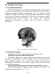
2. Product Overview 2.1. Product Definition N901 Smart Helmet is a wearable intelligent helmet for the actual combat needs of epidemic control and control in public places. This helmet integrates multiple advanced technologies such as infrared thermal imaging, AR (augmented reality) display, big data, communication sensing, and advanced aerospace technology. It is the first to implement mobile deployment-based control scenarios.
Fast temperature measurement and strong environmental adaptability Automatic temperature measurement of multiple targets both indoors and outdoors. Ultra-long battery life Equipped with high-energy density battery and high efficiency energy system to meet the long-running operation requirements in mobile scenarios.
Field of View Resolution Wi-Fi Bluetooth GPS Battery capacity Battery Life Voltage Charging Current Fast Charge Storage 78° 1080P@30fps Data Communication Frequency IEEE 802.11 b/g/n, 2.4GHz BT 4.0, backward compatible with 3.0, 2.1, supporting BLE Support GPS/AGPS/GLONASS Electrical Characteristics 5000 mAh Temperature measurement mode: up to 5 hrs. QR code /License plate recognition /Face recognition mode: 3 hrs. Standby time: 24 hrs. DC3.7~4.2V DC5.
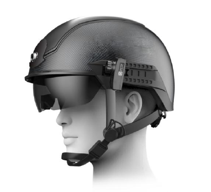
Frame Temperature Measurement Range Margin of Error Temperature measurement mode: 36 ºC ~42 ºC; Thermal imaging mode: -20~120 ºC ±0.3 ºC 2.4. Product Composition N901 Smart Helmet is mainly composed of helmet body, hardware platform, AR display module, infrared thermal imaging module and battery.
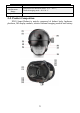
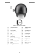
Figure 2. Parts of the Smart Helmet. [1] Visible light camera [12] The Bluetooth key [2] Overlay [13] TYPE-C port [3] Safety goggles.
3. Wear and Adjust 3.1. Wear the Smart Helmet 1) Connect the thermal imaging module to the connector plug; Figure 3. Connect thermal imaging module to connector 2) Push the thermal imaging temperature measurement module from back to front along the left guide rail of the helmet; Figure 4. Install the thermal imaging module on the guide rail 3) Connect the Type-C cable of the thermal imaging module to the TYPE-C socket of the helmet.
Figure 5. Connection of thermal imaging module 4) Select appropriate-thickness liner in the helmet according to your head size. 5) Adjust the tightness of the helmet strap. 6) Put on the smart helmet and fasten the buckle. 7) Turn the head lock knob to an appropriate position. 8) Put on the earphone. 3.2. Retract and Extend the Safety Goggles To open the goggles, gently lift the safety goggles from both sides (pushing position as show in Figure 4).
Figure 6. Pushing position of safety goggles Figure 7. Retracted and Extending State of safety goggles. 3.3. Adjust the AR Glasses. The AR glasses adapt the right monocular only, which is fixed to the interior of the safety goggles. The position of AR display screen can be fine-tuned by adjusting the arms of the AR glasses to ensure that the AR display screen is in complete and clear vision.
goggles should be avoided). Figure 8.
4. User Guide The N901 Smart Helmet can be controlled by whether the Android OSbased APP “Smart Helmet” or “Smart Watch”. 4.1. Power On Press and hold the On/Off button for three seconds, the helmet is power on with the RED indicator lighting up. Figure 9. Schematic diagram of power switch position 4.2. Controlled by the Android OS-based APP “Smart Helmet” 4.2.1. APP installation The N901 Smart Helmet can be controlled by the Android OSbased APP “Smart Helmet”. 1) Download APP: A.
Figure 10. The product identification card on the side of the carrying bag B. Go to the official website of Smart Helmet and download it from the "Support" section. 2) Name of the installation package: “AI_PHONE_v1.1.39.4_21_4_release.apk” 4.2.2. Bluetooth Connection These steps need to be executed only for the first time connection between the smart phone and the smart helmet; 1) Turn on Bluetooth on the smart phone 2) Open “Smart Helmet” App.
Figure 11. Bluetooth pairing pop-up dialog box and parameter setting page 5) If the connection failed, please try the following: A. Inspect the start-up state of the helmet and device and ensure that the Bluetooth is enabled and is not connected to other Bluetooth device. B. Press and hold the Bluetooth button on the left of the helmet, and click “Pair” again. C. If the problem is still unresolved, please restart the helmet and “Smart Helmet” App and try it again.
Bluetooth; Step 2: The calibration assisting person stands 1 meter in front of the thermal imager. Step 3: Adjust the center of the screen to target the ears or forehead of the assisting person, and click “One-Click Calibration”. The quick calibration is completed as “Calibration complete” prompting on the screen. Figure 12. One-Click Calibration Interface Note: Temperature measurement can be started till 5~10 minutes after the boot when the measurement accuracy has already been stabilized.
may be accompanied by a short-time video lag. During the whole calibration process, the center of the screen must be targeted at the uncovered forehead or ears of the assisting person. Otherwise, the calibration result may leave a large margin error. During the calibration process, the calibration assistant person needs to stand still until the calibration is completed.
Figure 13. Parameter setting interface of manual calibration Note: Temperature measurement can be started till 5~10 minutes after the boot when the measurement accuracy has already been stabilized.
Figure 14. Rainbow mode VS Iron Gray mode 4.2.6. Working modes The N901 standard version provides only two working mode of “single-person temperature measurement mode” and “large-crowd temperature measurement mode”. The specific working mode can be confirmed through the “Mode” setting page in the App. Figure 15. Selecting page of working modes 4.3. Controlled by the Smart Watch 4.3.1.
The upper key of smart watch is for the power control, you can long press for power on-off and short press for the screen rest or light. The down key is for the return operation, you can long press to take the picture and short press to go back to the previous menu. The screen will be unlocked by clicking the middle of dial. Then swipe from left to right to enter the main interface of the watch. And click the “Smart Helmet” App to enter the main control interface of the helmet.
Figure18. The Bluetooth connection interface of Smart Watch The one-way arrow in the figure above indicates that the operation is in front and back order. 4.3.3. Parameter Setting Switch the functions of “One-click calibration”, “Correction”, “Color plate model”, “Temperature unit” and so on by parameter setting, and press the “down key” to open the save parameter dialog box. At the same time, it is unnecessary to change the calibration parameters manually after one key calibration.
Figure19. Parameter setting interface of the smart watch One-way arrow means to operate in front and back order, the two-way arrow indicates that the operation can be switched repeatedly. And the central interface pointed by green arrow can appear after pressing the “down key”. Note: Temperature measurement can be started till 5~10 minutes after the boot when the measurement accuracy has already been stabilized.
calibration or manual calibration procedure. 4.3.4. Working modes The helmet can be controlled to perform different tasks by selection of different working modes. See the section 4.4 for the details of function introduction. Figure20. Function interface of the smart watch One-way arrow means to operate in front and back order, the two-way arrow indicates that the operation can be switched repeatedly 4.4. Introduction of working modes 4.4.1.
Figure 21. Single-person temperature measurement mode The default warning range is 37.3 °C ~ 42 °C. When the highest temperature detected in the center of the screen locates in this range, it will trigger an audible and visual alarm. This mode can be used for accurate temperature measurement in all scenarios, particularly suitable for the fast temperature measurement outdoors at daytime or in environment with complicated thermal radiation sources.
Figure 22. Large-crowd temperature measurement mode Note: The thermal imaging module could not distinguish the properties of the imaging objects at current version. If the lamp box, water cup or metal parts exposed to direct sunlight appear in the screen, the temperature value of these parts may be displayed and the readings will be affected. Therefore, single-user mode is recommended for the complicated environment. 4.4.3.
Figure 23. QR code recognition mode 4.4.4. QR code & temperature measurement mode Scan the QR code to acquire the personal information first, and take a temperature measurement of the person within 3 seconds. The personal temperature info will be automatically recorded into database in real time, allowing paperless data logging, safe distance and fast passing. Note: Open the user's QR code and scan it using the visible light camera.
Figure 24. QR code & temperature measurement mode 4.4.5. License plate recognition mode Recognize the vehicle license plate, identify and alert unregistered vehicles or suspect vehicles recorded in database. (For mainland China use only.) Figure 25.
The license plate information displayed on the AR display screen, indicates that the license plate recognition has been completed; The license plate database needs to be established before use (See section 4.6.4 for details); The information displayed depends on the tags and rules in the database. 4.4.6.
Figure 27. Thermographic diagnostic Imaging mode 4.4.8. Night-vision/Facility inspection mode Thermal imaging scanning of industrial facilities, HVAC equipment, pipelines and electronic equipment, is applicable for industrial inspection and night vision inspection scenes such as assisting users in qualitative analysis, finding targets or locations with abnormal temperature, searching for people stranded at night and qualitatively analyzing facility working conditions. . Figure 28. Night-vision Figure 29.
institutions to manage their black and white lists of employees and visitors. The person in the white list is shown as green mark, and the person in the black list is shown as the red mark. Local face database supports up to 10,000 face data. Please refer to section 5.3 for details for the face database setup. Figure 30. Face recognition mode 4.4.10.
Figure 31. The main interface of the tool After USB connection, the helmet screen can display once clicking the “Connecting device” on the main interface. 4.5.2. Wireless projection After USB connection is completed, you can click the “Wireless Projection” on the main interface to set “WLAN” to ensure that the smart helmet and computer are in the same LAN. Then click “back” and disconnect the connection cable, you can click “wireless projection” to display the helmet screen.
Figure 32.
4.5.3. Build Facial Database The facial image is required to be a JPG format file of 400x500 pixels.
as “Template Download” 、 “Import” 、 “Delete” and so on through entering the interface of License plate by clicking the “File management” button of the main interface. Figure 34. Operation interface of License plate database Template Download: Download the template of “license plate”, the helmet supports license plate database in the EXCEL format, in which following information should be included: Figure 35.
owner_phone other flag Owner phone number User-defined information to display Symbol colors Optional Necessary information, words are limited around 10. Necessary information: 1 means red, alert 2 means green, normal 0 means yellow, unregisted/not existing in database Import: Import the file of license plate; Delete: Delete the file of license plate. 4.5.5. Video Export To avoid occupying too much storage space, the video files should be exported in time.
Figure 36. Operation interface of Video Export 4.5.6. Generate QR Code After the USB connection is successful, you can enter the QR code generation interface by clicking "Generate QR code" on the main interface, then you can make the "QRcode template", "Generate QR code" and "download QRcode" and other operations. QRcode template: Download "QRcode" template file; Generate QR Code: load information file to generate QR code; Download QR Code: export the generated QR code.
Figure 37. Operation interface of QRcode Generation 4.5.7. Temperature data export The temperature data that generated under the QR code temperature measurement mode can be exported. After the USB connection is successful, you can enter the "Thermometry" operation interface by clicking the "File management" of the main interface, then you can make the "Export", "Delete" and "Clear" operations.
Figure 38. Temperature data export 4.5.8. Software update The software upgrade package can be downloaded through the XXXofficial website. After the helmet is connected to the computer by USB connection, click “Upgrade” on the main interface. First select “KCHELMETUPDATE_v1.1. 38_6_release.apk” to upgrade. Once the updating is completed, then select the package "AI_KCHELMET_ssv1.1.38.4_32_4_release.apk" to update.
Figure 39. Operation interface of Software Upgrade 4.6. Standby and Power down Short press the power button, the AR display goes out, and the helmet enters the standby state; short press the power button again, the AR display lights on, and the helmet enters the working state. Hold the power button for 3 seconds to shut down the helmet.
5. Cautions 5.1. Battery Usage Under any circumstances, please do not modify the built-in battery by yourself to avoid causing damage to the battery. Do not put the battery into fire or any other high temperature place, otherwise it will cause fire or explosion of the battery. The battery cannot be used for other purposes. Do not use any damaged charger or battery.
6. Frequently Asked Questions 6.1. Hardware FAQ 6.1.1. Unable to boot 1) Make sure the battery is installed correctly. 2) Connect the power cord to charge. If the power indicator is on, charge the helmet for at least 20 minutes to ensure that the battery has enough power to power on. If the power indicator does not light on after power cable connection, the power supply module may be damaged. 3) Press and hold the power button to try to power on.
6.1.5. Short battery life Under normal circumstances, the battery life of helmet is up to 5 hours for temperature measurement ; and the battery life will be shortened to 3 hours in heavy load modes when the visible light camera and infrared thermal imaging module work at the same time, e.g. in the license plate recognition or QR code recognition mode. A possible cause for the significant shorter battery life is that the battery is not fully charged.
A: Press and hold for 3 seconds to boot. 6.2.3. Questions about wearing adjustment 1) Q: How many places can I adjust when wearing the smart helmet? A: A. Strap Length B. The optical waveguide AR glasses are installed on the safety goggles, and the AR glasses position can be adjusted by adjusting the AR glasses arm. (As the space for extending and retracting of the AR glasses is limited, large-range adjustment of the AR glasses on the safety goggles should be avoided).
7. Notices and after-sales service 7.1. Disclaimer 1) Please read this manual carefully before usage to fully understand your legal rights and responsibilities; otherwise, it may cause property damage or personal injury. The company shall not be liable for any direct or indirect property damage and personal injury caused by failure to use this product in accordance with this manual. 2) The company has done its best to ensure the content in this manual is accurate and reliable.
modify the helmet shell. 3) This product requires the power to be turned off during the charging process. The product will have its warranty void if you use the product while it is being charged and cause damage. 4) Damage to the product and its subsidiary systems, due to nonquality reasons such as incorrect use and sabotage, are not covered by the warranty.
8. FCC Warning Any Changes or modifications not expressly approved by the party responsible for compliance could void the user's authority to operate the equipment. This device complies with part 15 of the FCC Rules. Operation is subject to the following two conditions: (1) This device may not cause harmful interference, and (2) this device must accept any interference received, including interference that may cause undesired operation.