LA-WE3L User manual File No.:20200907-V2.0 ※ This document shall come into effect on the date of approval and shall not be reproduced without permission.
Contents 1 RRODUCT OVERVIEW........................................................................4 1.1 PODUCT CHARACTERISTICS............................................................4 1.2 MAIN APPLICATION FIELDS.............................................................4 3 OVERALL DIMENSION....................................................................... 6 4 PCB PACKAGE SIZE............................................................................. 6 5 PIN DEFINITION........................
8.2 APPLICATION OF THREE-WAY RGB LIGHT 8.3 APPLICATION OF BULB LAMP WITH STRIP........................ 12 IIC INTERFACE.....................13 9 APPLICATION SCENARIOS.............................................................
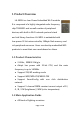
1 Product Overview LA-WE3L is a Low-Power Embedded Wi-Fi module. It is composed of a highly integrated radio frequency chip TR6260S1 and a small number of peripheral devices, with built-in Wi-Fi network protocol stack and rich library functions. LA-WE3L is embedded with low-power 32-bit microcontroller, 1Mbyte flash memory and rich peripheral resources. Users can develop embedded WiFi products to meet their own needs based on these. 1.1 Product Characteristics 2.4GHz,EEE802.
It is used in bulb lamp, ceiling lamp, wall switch, wall socket, adapter socket and other smart home products.
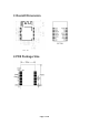
3 Overall Dimension Unit:mm 4 PCB Package Size Page 2 of 8
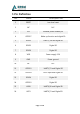
5 Pin Definition No. Name Description No. 1 RESET Low level reset 2 NC N.C. 3 EN Module power enable pin 4 GPIO17 Wake up function and digital IO 5 GPIO2 UART1_ RX and digital IO 6 GPIO1 Digital IO 7 GPIO0 Digital IO 8 VDD Power supply 3.3V 9 GND Power ground 10 NC N.C.
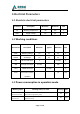
6 Electrical Parameters 6.1 Absolute electrical parameters Parameters Description Minimum Maximum Unit TS Working temperature -20 105 ℃ VDD Supply voltage -0.3 3.6 V 6.2 Working conditions Parameters Description Minimum Typical Minimum Unit VDD Working voltage 3.0 3.3 3.6 V VDDIO IO voltage 1.8 3.3 3.6 V VIL IO low level input -0 - 0.3*VIO V VIH IO high level input 0.7*VIO - VIO V VTH COMS threshold - 0.5 VIO Imax IO maximum drive V 12 mA capability 6.
etwork connection The module is in the networking state, and the Wi-Fi indicator is status always on Networking attempt The module is in the working state of disconnection (trying to connect to the network), and the Wi-Fi indicator is always off Page 4 of 8 54 mA 65 mA
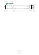
7 RF Characteristics 7.1 Basic RF characteristics Basic RF characteristics Parameter item Working Detailed description 2.412~2.462GHz frequency WiFi standard IEEE 802.11b/g/n(Channel1-11) Data transmission 11b:1,2,5.5,11 (Mbps) rate 11g:6,9,12,18,24,36,48,54(Mbps) 11n:HT20 MCS7 Antenna type PCB antenna (default) 7.
7.3 Wi-Fi receiving sensitivity RX receiving sensitivity Parameter Minimum Mode Typical Rate Maximu Unit m dBm F average output 11M - -88.0 - dBm 54M - -74.0 - dBm HT20-MCS7 - -70.6 - dBm -10 - 10 ppm power,802.11b CCK Mode F average output power,802.11g OFDM Mode F average output power,802.
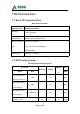
8 Application Schematic Diagram 8.1 Dimming application of five PWM lamps Cold color Red light Blue light Green light Warm color The module can support five PWM channels, and the user can select the corresponding PWM interface according to the actual product situation. The corresponding color can also modify the customized firmware according to the actual needs; 8.
8.
This device complies with Part 15 of the FCC Rules. Operation is subject to the following two conditions: (1) this device may not cause harmful interference, and (2) this device must accept any interference received, including interference that may cause undesired operation. Any changes or modifications not expressly approved by the party responsible for compliance could void the user’s authority to operate the equipment.