
User's Manual
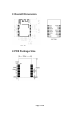
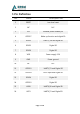
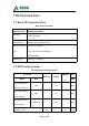
Table Of Contents

Page 3 of 8
5 Pin Definition
1
RESET
Low level reset
2
NC
N.C.
3
EN
Module power enable pin
4
GPIO17
Wake up function and digital IO
5
GPIO2
UART1_ RX and digital IO
6
GPIO1
Digital IO
7
GPIO0
Digital IO
8
VDD
Power supply 3.3V
9
GND
Power ground
10
NC
N.C.
11
GPIO13
UART1_TX and Digital IO
12
GPIO14
ADC input and Digital IO
13
GPIO4
Digital IO
14
GPIO13
Digital IO
15
U0RX
UART0_RX and Digital IO
16
U0TX
UART0_TX and Digital IO
No. Name Description No.