
Data Sheet
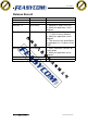
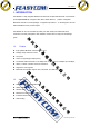
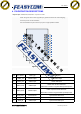
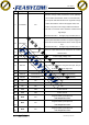
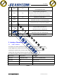
Table Of Contents

深圳市飞易通科技有限公司
www.feasycom.com
FSC-BT826
26
PIO3
I/O
Programmable input/output line
*
The I/O port for reuse.
27
PIO4
I/O
Programmable input/output line
Alternative Function: BT Power Mode, low level in run
mode, it will be set to high level when fall asleep.
28
PIO5
I/O
With the use of the Pin 9.
29
PIO6
I/O
Programmable input/output line
Alternative Function: I
2
C CLK line (Default)
30
PIO7
I/O
Programmable input/output line
Alternative Function: I
2
C DATA line (Default)
31
PIO8
I/O
With the use of the Pin 10.
32
PIO9
I/O
Programmable input/output line
Alternative Function: LED(Default)
33
PIO10
I/O
Programmable input/output line
Alternative Function: BT Status(Default)
34
PIO11
I/O
Programmable input/output line
Table 2
5. Interface Characteristics
5.1 UART Interface
Four signals are used to implement the UART function. When FSC-BT826 is connected to
another digital device, UART_RX and UART_TX transfer data between the two devices. The
remaining two signals, UART_CTS and UART_RTS, can be used to implement RS232
hardware flow control where both are active low indicators.
The interface consists of four-line connection as described in below:
Signal name
Driving source
Description
UART-TX
FSC-BT826 module
Data from FSC-BT826 module
UART-RX
Host
Data from Host
UART-RTS
FSC-BT826 module
Request to send output of FSC-BT826 module
UART-CTS
Host
Clear to send input of FSC-BT826 module
Table 3