N720 Hardware User Guide N720 Hardware User Guide Version 1.3 Copyright © Neoway Technology Co.
N720 Hardware User Guide Copyright © 2017 Neoway Technology Co., Ltd. All rights reserved. is the trademark of Neoway Technology Co., Ltd. All other trademarks and trade names mentioned in this document are the property of their respective holders. Remarks This document is intended for system engineers (SEs), development engineers, and test engineers. The information in this document is subject to change without notice due to product version update or other reasons.
N720 Hardware User Guide Revision Record Version Changes V1.0 Initial draft 2016-08 V1.1 Added bands information of different areas 2016-09 V1.2 Modified pin the description 2016-10 V1.3 Modify the UIM card part and delete the UIM2 part 2016-12 Improve band information Modify part of the pin definition (the original pin78 RING, pin80 LIGHT are modified to pin13 RING, pin83 LIGHT. Pin13 and pin83 are NC) Modify part of description Copyright © Neoway Technology Co.
N720 Hardware User Guide Contents 1 Introduction to N720 ........................................................................................................ 1 1.1 Overview ........................................................................................................................................... 1 1.2 Block Diagram .................................................................................................................................. 2 1.3 Features ............................
N720 Hardware User Guide 5.2 TX Power and RX Sensitivity ....................................................................................................... 36 6 Mechanical Feature ........................................................................................................ 37 6.1 Dimensions ..................................................................................................................................... 37 6.2 PCB Foot Print ...............................................
N720 Hardware User Guide Table of Figures Figure 1-1 N720 block diagram ........................................................................................................... 2 Figure 2-1 Top view of N720 ................................................................................................................ 5 Figure 2-2 Current peaks and voltage drops ................................................................................... 14 Figure 2-3 Capacitors used for the power supply ........
N720 Hardware User Guide Figure 8-1 Temperature curve ............................................................................................................ 40 Copyright © Neoway Technology Co.
N720 Hardware User Guide Table of Tables Table 1-1 N720 baseband and wireless features ............................................................................. 2 Table 2-1 N720 dimensions ................................................................................................................. 5 Table 2-2 N720 pin description ............................................................................................................ 6 Table 2-3 GPIO .............................................
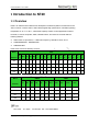
N720 Hardware User Guide 1 Introduction to N720 1.1 Overview N720 is an industrial 4G module that is developed on Qualcomm platform. Its dimensions are 30mm x 28 mm x 2.8mm and it is with industrial-grade high-performance: ultra-wide operating temperature of -40 ℃ to +85 ℃, electrostatic capacity of 8KV. It is well applicable to electric terminals, in-vehicle computers, POS, industrial routers, and other IoT terminals with the following features: ARM Cortex-A7 processors, 1.
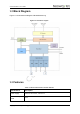
N720 Hardware User Guide 1.2 Block Diagram Figure 1-1 shows the block diagram of N720 Modular only, Figure 1-1 N720 block diagram 1.3 Features Table 1-1 N720 baseband and wireless features Specifications Description Power supply VBAT: 3.3V to 4.3V, TYP: 3.8 V Current in sleep mode 4mA Copyright © Neoway Technology Co.
N720 Hardware User Guide Operating temperature: -40°C to +85°C Temperature Limited: -40°C to +85°C Storage temperature: -40°Cto +85°C ARM Cortex-A7 processor Processor Main frequency: 1.
N720 Hardware User Guide EDGE1800MHz: +27.5dBm (Power Class E2) EDGE1900MHz: +27.5dBm (Power Class E2) UMTS: 24dBm (Power Class 3) LTE: +23dBm (Power Class 3) Antenna feature 50Ω impedance UART At most 4 Mbps, 1 group UIM 1 groups, 1.8V/3V dual-voltage adaptive USB 1 group of USB2.0 high-speed interface ADC 2 groups of 16-bit ADC, input voltage ranging from 0.1 to 1.7V Copyright © Neoway Technology Co.
N720 Hardware User Guide 2 Application Interfaces N720 adopts 100-pins LGA encapsulation. 2.1 Specifications and Pin Definition Table 2-1 N720 dimensions Specifications N720 Dimensions 30mm*28 mm*2.8mm(H*W*D) Weight 5.1g Package 100-Pin LGA Figure 2-1 Top view of N720 Copyright © Neoway Technology Co.
N720 Hardware User Guide 2.2 Pin Description IO: input/output DI: Digital input DO: Digital output PI: Power input PO: Power output AI: Analog input AO: Analog output Table 2-2 N720 pin description Name Pin I/O Function Level Feature (V) 27, 28, 29 PI Main power supply input Vmax=4.3V Power Domain Remarks Power Supply VABT The power supply can provide up to 3A current VDDIO _1P8 45 GND 1, 14, 17, 20, Copyright © Neoway Technology Co., Ltd PO 1.8 V power supply output Vnorm=1.
N720 Hardware User Guide 26, 30, 31, 44, 49, 74, 75, 77, 91, 93, 95, 97, 98, 99, 100 Power on/off and reset RESET 32 DI Reset input 1.8V VIL min=-0V; PWRKEY 33 DI Power ON/OFF VIL max=0.5V; 1.8V VIH min=1.2V; VIH max=2.1V; PON_TRIG 34 DI PON_TRIG Low level triggers the ON status and can control the power off and reset. Low level triggers the ON status. It is pulled up by an internal 200 KΩresistor. High level triggers the ON status. 1.8V It is pulled up by an internal 200 KΩresistor.
N720 Hardware User Guide VIL max=0.45V; VIH min=1.35V; VIH max=2.1V UART2_CTS 51 DI Clear to send VOL max=0.45V; VOH min=1.35V; 1.8V Leave it disconnected if you do not use it. 1.8V Leave it disconnected if you do not use it. VIL min=-0.3V; UART2_RTS 52 DO Request to send VIL max=0.45V; VIH min=1.35V; VIH max=2.1V UIM 1.8V USIM: Vmax = 1.9V ; Vmin = 1.7V; VUIM 35 PO UIM power supply output 3V USIM: 1.8V/3V Vmax = 3.05V; Compatible with 1.8/3V UIM card Vmin = 2.7V; IO max =50mA 1.
N720 Hardware User Guide VOL max = 0.4V; VOH min = 2.6V; UIM_DATA 1.8V USIM: VIL max = 0.6V; VIH min = 1.2V; VOL max = 0.45V; 36 IO UIM data input, output VOH min = 1.35V; 3V USIM: 1.8V/3V VIL max = 0.8V VIH min = 1.95V VOL max = 0.45V VOH min = 2.6V Compatible with 1.8/3V UIM card 1.8V USIM: VOL max = 0.45V UIM_CLK 37 DO UIM clock output VOH min = 1.35V 3V USIM: 1.8V/3V VOL max = 0.4V VOH min = 2.6V UIM_DETECT 39 DI UIM detect VIL min = -0.3V VIL max = 0.63V 1.
N720 Hardware User Guide USB_DM 41 IO USB data negative signal USB2.0 USB_DP 42 IO USB data positive signal USB2.0 VBUS 40 PI USB voltage test 3.3V~5.2V, typically 5V USB _ID 43 AI Identify host and device 88 AI Analog-to-digital signal conversion Vmax=1.7V Vmax=1.7V Used for firmware download and data transmission Differential trace for DM and DP 90Ω impedance resistance 1.8V Leave it disconnected if you do not use it.
N720 Hardware User Guide RING 13 DO Incoming call ring VOL max=0.45V; VOH min=1.35V; 1.8V Leave it disconnected if you do not use it. 1.8V Leave it disconnected if you do not use it. Other Pins VIL min=-0.3V; FORCE_USB_BOOT 48 DI Force to download and upgrade control pin VIL max=0.45V; VIH min=1.35V; VIH max=2.
N720 Hardware User Guide 73、78、80、 81、82、84、 85、86、87、 90、96 Copyright © Neoway Technology Co.
N720 Hardware User Guide 2.3 Power Control Interfaces Name Pin I/O Function Remarks VABT 17/18/1 9 P Main power supply input 3.3 V to 4.3 V (TYP: 3.8 V ) VDDIO_1P8 45 P 1.8 V power supply output Supply power for IO level shifting circuit. Load capability: <100 mA Advise to add ESD to protect while using. RESET 32 DI Reset input Low level PON_TRIG 34 DI PON_TRIG High level triggers the ON status PWRKEY 33 DI Power ON/OFF Low level triggers the ON status 2.3.
N720 Hardware User Guide Figure 2-2 Current peaks and voltage drops Figure 2-3 shows the reference design of the VRTC power supply. Figure 2-3 Capacitors used for the power supply In Figure 2-3, you can use TVS at D1 to enhance the performance of the module during a burst. SMF5.0AG (Vrwm=5V&Pppm=200W) is recommended.
N720 Hardware User Guide preferable if used in harsh conditions. You can use the EN pin on the LDO or DC/DC chipset to control the switch of the power supply as shown inFigure 2-4if a 5V power supply is used. MIC29302WU in Figure 2-4 is an LDO and outputs 3 A current to ensure the performance of the module. Figure 2-4 Reference design of power supply control The alternative way is to use an enhancement mode p-MOSFET to control the module's power, as shown inFigure 2-5.
N720 Hardware User Guide Q2 is added to eliminate the need for a high enough voltage level of the host GPIO. In case that the GPIO can output a high voltage greater than VCCIN - |VGS(th)|, where VGS(th) is the Gate Threshold Voltage, Q2 is not needed. Reference components: Q1 can be IRML6401 or low Rds(on) pMOSFET, which has higher, withstand voltage and drain current. Q2: a common NPN tripolar transistor, e.g. MMBT3904; or a digital NPN tripolar transistor, e.g. DTC123.
N720 Hardware User Guide Figure 2-6 Reference designs of separated power supply Never use a diode to make the drop voltage between a higher input and module power. Otherwise, Neoway will not provide warranty for product issues caused by this. In this situation, the diode will obviously decrease the module performances, or result in unexpected restarts, due to the forward voltage of diode will vary greatly in different temperature and current.
N720 Hardware User Guide Figure 2-7 Push switch controlling Figure 2-8 MCU controlling If the module is powered on but the power-on sequence has not been completed, the states of each pin are uncertain. The power-on sequence of the module is shown in Figure 2-9. Figure 2-9 N720 power-on/off sequence If your application does not require ON/OFF control, you can pull the PWRKEY pin down to GND through 1.5K resistor. Then the module can start automatically after it is powered on.
N720 Hardware User Guide not use the PWRKEY pin, it must be left disconnected. The PON_TRIG pin can trigger the ON status of the module by high level. Power-off Power off can be achieved through two methods, one is to use PWRKEY input pin; the other is to use RESET pin. 1. Use PWRKEY pin. Low-level pulse input for 2 seconds can trigger the power-off status of the module. This pin is pulled up internally. Its typical high-level voltage is 1.8 V. Leave this pin disconnected if you do not use it. 2.
N720 Hardware User Guide high-level voltage is 1.8 V. Leave this pin disconnected if you do not use it. If you use a 2.8V/3.3V IO system, it is recommended that you add a triode to separate it. Refer to the following design. Figure 2-11 Reset controlled by button Figure 2-12 Reset circuit with triode separating In a circuit shown in Figure 2-12, VDD_EXT=2.8V/3.3V/3.0V, R2=4.7K, R3=47K. Figure 2-13 shows the reset sequence. Figure 2-13 N720 reset sequence Copyright © Neoway Technology Co.
N720 Hardware User Guide 2.4 USB Interface Name Pin I/O Function Remarks VBUS 40 P USB voltage test 3.3V~5.2V, typically 5V USB_DM 41 IO USB data negative signal USB_DP 42 IO USB data positive signal USB2.0, used for firmware download and data transmission You can download programs for N720 and establish data communication for commissioning through the USB interface. If the module is used only as USB Device, the recommended USB circuit is shown in Figure 2-14.
N720 Hardware User Guide lines adopt differential trace design, in which the differential impedance is limited to 90 Ω characteristics impedance. Isolate the traces from other signal traces. 2.5 UIM Card Interface Name Pin I/O Function Remarks VUIM 35 PO UIM power supply output Compatible with 1.8/3 V UIM card A 10K resistor is required between VUIM and UIM-DATA.
N720 Hardware User Guide ESD protectors, such as ESD diodes or ESD varistors (with a junction capacitance of less than 33 pF), are recommended to be added on the SIM signals, especially in automotive electronics or other applications with badly ESD. Replace the ESD diodes with 27 pF to 33 pF capacitors connecting to GND in common applications. The ESD diodes or small capacitors should be close to UIM card. N720 supports SIM card detection. UIM_DETECT is 1.8V interrupt pins.
N720 Hardware User Guide 2.6 GPIO N720supports UART. You can configure the GPIO to meet your requirements for connecting to different devices. For the open multi-function GPIO interface, please inquiry our technical support engineers. The level of the module interface is 1.8 V. Table 2-3lists GPIO pins.
N720 Hardware User Guide Figure 2-17 Reference design of the UART interface If the UART does not match the logic voltage of the MCU, it is recommended that you add a level shifting circuit outside of the module as shown in Figure 2-18. Figure 2-18 Recommended level shifting circuit Copyright © Neoway Technology Co.
N720 Hardware User Guide Components: R2/R4: 2K-10K. The greater the UART baud rate is, the lower the R2 value is. R1/R3: 4.7K-10K The greater the UART baud rate is, the lower the R3 value is. Q1: MMBT3904 or MMBT2222 High-speed transistor is better. MCU_UTXD and MCU_URXD are respectively the TX and RX ports of the MCU while TXD and RXD are respectively the TX and RX ports of the module.
N720 Hardware User Guide When the module is running, the LED indicator is driven by the NET_LIGHT pin to indicate different module status with its various blink behaviors. N720 supports multiple blink style and you can configure it using AT commands. 2.6.4 DTR Generally, DTR is used to control sleep mode together with AT commands. Enable the sleep mode function by AT command. Then pulling DTR low will bring the module into sleep mode if the module is idle.
N720 Hardware User Guide Figure 2-20 RING indicator for incoming call 30 ms 30 ms 5s SMS: Upon receipt of SMS, the module outputs one 35 ms low pulse. Figure 2-21 RING indicator for SMS 35 ms 2.7 Commissioning Interfaces To facilitate software update and commissioning, reserve the commissioning interfaces. 2.7.1 FORCE_USB_BOOT The module can enter the fastboot mode by short connecting the FORCE_USB_BOOT pin and VDDIO_1P8V during the startup.
N720 Hardware User Guide 3 RF Interface Name Pin I/O Function ANT_MAIN 76 AI/O 2G/3G/4G main antenna ANT_GPS 92 AI GPS antenna ANT_AUX 94 AI 4Gdiversity aerial Remarks 50Ω characteristic impedance 3.1 2G/3G/4G RF Design and PCB Layout ANT_MAIN and ANT_AUX is the antenna pin of N720. A 50 Ω antenna is required. VSWR ranges from 1.1 to 1.5. The antenna should be well matched to achieve best performance.
N720 Hardware User Guide Big RF solder pad can result in great parasitic capacitance, which will affect the antenna performance. Remove the copper on the first and second layers under the RF solder pad. Figure 3-2 Recommended RF PCB design If you adopt RF antenna connections, the GSC RF connector MM9329-2700RA1 from Murata is recommended..Figure 3-3shows the encapsulation specifications.
N720 Hardware User Guide 3.2 GPS RF Design and PCB Layout 3.2.1 GPS Impedance The 92nd pin is the GPS interface of the module, which also requires a 50 Ω. The PCB layout for GPS is similar to that for GPRS. For details, refer to the previous section. Figure 3-5 shows the internal structure of the GPS RF.
N720 Hardware User Guide as possible. The power supply of the active antenna is fed by the 100 nH inductance through the signal traces. Common active antenna requires 3.3V to 5V power supply. Though the active antenna has a low power consumption, it requires stable and clean power supply. You are advised to use high-performance LDO to supply power for the antenna through a 100 nH inductance, as shown inFigure 3-6.
N720 Hardware User Guide 4 Electric Feature and Reliability 4.1 Electric Feature Table 4-1 N720 Electric Feature Module Status Minimum Value Typical Value Maximum Value Vin 3.3V 3.8V 4.3V Iin / / 3A VBAT If the voltage is too low, the module might fail to start. If the voltage is too high or there is a voltage burst during the startup, the module might be damaged permanently. If you use LDO or DC-DC to supply power for the module, ensure that it output at least 3 A current. 4.
N720 Hardware User Guide 4.3 ESD Protection Electronics need to pass sever ESD tests. The following table shows the ESD capability of key pins of our module. It is recommended that you add ESD protection to those pins in accordance to the application to ensure your product quality when designing your products.
N720 Hardware User Guide 5 RF Feature 5.1 Work Band Table 5-1 N720 work band Work band Uplink Downlink GSM850 824~849MHz 869~894MHz PCS1900 1850~1910MHz 1805~1880MHz UMTS B2 1850~1910MHz 1805~1880MHz UMTS B4 1710~1755MHz 2110~2155MHz UMTS B5 824~849MHz 869~894MHz LTE-FDD B2 1850~1910MHz 1805~1880MHz LTE-FDD B4 1710~1755MHz 2110~2155MHz LTE-FDD B5 824~849MHz 869~894MHz LTE-FDD B7 2500~2570MHz 2620~2690MHz LTE-FDD B12 699.7 – 715.3 MHz 729.7– 745.
N720 Hardware User Guide 5.2 TX Power and RX Sensitivity Table 5-2 N720 RF power and RX sensitivity Band Transmitting Power Receiving Sensitivity GSM850 34 dBm <-108 dBm PCS1900 31.
N720 Hardware User Guide 6 Mechanical Feature 6.1 Dimensions Figure 6-1 Dimensions of N720 Copyright © Neoway Technology Co.
N720 Hardware User Guide 6.2 PCB Foot Print Figure 6-2 N720PCBFoot Print(Top View) A test point is reserved at the Silk Area. It is recommended that you add a layer of white ink in case short circuit. Do not lay out any trace under the JTAG pin. Copyright © Neoway Technology Co.
N720 Hardware User Guide 7 Mounting and Packaging 7.1 Mounting the Module onto the Application Board N720 is compatible with industrial standard reflow profile for lead-free SMT process. The reflow profile is process dependent, so the following recommendation is just a start point guideline: Only one flow is supported. Quality of the solder joint depends on the solder volume. Minimum of 0.12 mm to 0.15stencil thickness is recommended. Use bigger aperture size of the stencil than actual pad size.
N720 Hardware User Guide 8 SMT TemperatureCurve Figure 8-1 Temperature curve X: Time (s) Y Temperature (°C) Technicalparameters: Ramp up rate: 1to 4°C/sec; Ramp down rate: -3 to-1°C/sec Soaking zone: 150-180°CTime: 60-100s Reflow zone:>220°CTime: 40-90s Peak temperature: 235-250°C It is not recommended that you use the kind of solder paste different from our module technique. The melting temperature of solder paste with lead is 35°Clower than that of solder paste without lead.
N720 Hardware User Guide 9 Abbreviations ADC Analog-Digital Converter CPU Central Processing Unit DTR Data Terminal Ready EGSM Enhanced GSM ESD Electronic Static Discharge GPRS General Packet Radio Service GSM Global Standard for Mobile Communications IMEI International Mobile Equipment Identity LED Light Emitting Diode PCB Printed Circuit Board RF Radio Frequency SIM Subscriber Identification Module UART Universal asynchronous receiver-transmitter Copyright © Neoway Technology Co
N720 Hardware User Guide FCC Information This equipment has been tested and found to comply with the limits for a Class B digital device, pursuant to part 15 of the FCC rules. These limits are designed to provide residential protection against harmful interference in a residential installation. This equipment generates, uses and can radiate radio frequency energy and, if not installed and used in accordance with the instructions, may cause harmful interference to radio communications.