
User's Manual


N
720 Hardware User Guide
Copyright © Neoway Technology Co., Ltd v
Table of Figures
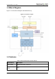
Figure 1-1 N720 block diagram ........................................................................................................... 2
Figure 2-1 Top view of N720 ................................................................................................................ 5
Figure 2-2 Current peaks and voltage drops ................................................................................... 14
Figure 2-3 Capacitors used for the power supply ........................................................................... 14
Figure 2-4 Reference design of power supply control .................................................................... 15
Figure 2-5 Reference design of power supply controlled by p-MOSFET .................................... 15
Figure 2-6 Reference designs of separated power supply ............................................................ 17
Figure 2-7 Push switch controlling .................................................................................................... 18
Figure 2-8 MCU controlling ................................................................................................................ 18
Figure 2-9 N720 power-on/off sequence .......................................................................................... 18
Figure 2-10 N720 power-off sequence ............................................................................................. 19
Figure 2-11 Reset controlled by button ............................................................................................. 20
Figure 2-12 Reset circuit with triode separating .............................................................................. 20
Figure 2-13 N720 reset sequence ..................................................................................................... 20
Figure 2-14 USB circuit ....................................................................................................................... 21
Figure 2-15 Reference design of SIM card interface ...................................................................... 22
Figure 2-16 Encapsulation .................................................................................................................. 23
Figure 2-17 Reference design of the UART interface .................................................................... 25
Figure 2-18 Recommended level shifting circuit ............................................................................. 25
Figure 2-19 LED indicator driven by transistor ................................................................................ 26
Figure 2-20 RING indicator for incoming call ................................................................................... 28
Figure 2-21 RING indicator for SMS ................................................................................................. 28
Figure 2-22 Reference design of the fast boot interface ................................................................ 28
Figure 3-1 Reference of antenna matching design ......................................................................... 29
Figure 3-2 Recommended RF PCB design ..................................................................................... 30
Figure 3-3 Encapsulation specifications of Murata RF connector ................................................ 30
Figure 3-4 RF connections ................................................................................................................. 30
Figure 3-5 GPS RF structure ............................................................................................................. 31
Figure 3-6 Power supply reference for active antenna .................................................................. 32
Figure 6-1 Dimensions of N720 ......................................................................................................... 37
Figure 6-2 N720PCBFoot Print(Top View) ....................................................................................... 38