
User's Manual


Information in this document is subject to change without prior notice. Page
10 of 13
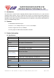
e). Model: GWF-1M01-50-F-2.0-7-1; GWF-1M01-33-F-2.0-7-1
C
o
n
n
e
c
t
o
r
L
E
D
S
h
i
e
l
d
C
a
s
e
S
h
i
e
l
d
C
a
s
e
L
E
D
R
F
U
n
i
t
:
m
m
Figure 16: Bottom side 7–Pin 2.0mm pitch 90 degree pin header interface.
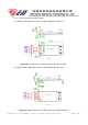
3.4.2 Pin definition:
Pin-out 7-pin 2.0mm pitch pin header 4-pin 2.0 or 2.54mm pitch pin header
1 WPS control
GND (Ground)
2
RF/TX ON/OFF control DP (USB data+)
3
GND (Ground) DM (USB data-)
4
DP (USB data+) VCC (3.3 VDC or 5.0VDC)
5
DM (USB data-) N/A
6
VCC (3.3 VDC or 5.0VDC) N/A
7
LED* (Wireless TX status) N/A
3.4.3 RF output Connection Information
If the I-PEX RF connection is selected, a 50 ohm external antenna connects to the module
RF output via an I-PEX MHF receptacle (RF connector). ( Part No: 20279-001E-01).