
Users Manual

4
RA
K20
11
RAK3401
4
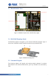
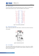
2.3 Board Realistic View
Figure 1: RAK3401’s top layer (left), and bottom layer (right).
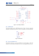
2.4 RAK3401 Mounting Sketch
The RAK3401 module is designed to work with the RAK5505 baseboard. Figure 2
shows how a RAK3401 module should be mounted on top of the RAK5505.
Figure 2: RAK3401 mounting sketch.
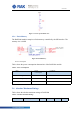
2.5 Schematic Diagram
The following chapters will describe the breakout module schematic. It includes
WisConnector, core module, SWD interface, power up automatic reset, and memory
flash.