
Users Manual

5
RA
K20
11
RAK3401
5
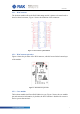
2.5.1 WisConnector
The breakout module allows the RAK3400 stamp module’s pinout to be transferred to
board-to-board connector, Figure 3 shows the definition of this connector.
Figure 3: WisConnector pin definition.
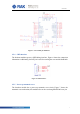
2.5.2 WisConnector pin order
Figure 4 shows the pin order of the WisConnector, which is located in the bottom layer
of the module.
Figure 4: WisConnector pin order.
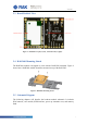
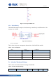
2.5.3 Core module
The breakout module itself has a RAK3400 at its core, Figure 5 shows the core module
pin and connection information, by default, the NFC function is disabled for conserve
the low power characteristic.