¢Guard EG2233: Installation and Set-up Procedures A. Introduction: EG2233 is 3 wireless communication system transmitting and receiving signals via radio frequencies. The standard operating center of frequency is 9.5MHz with bandwidth of 1 MHz Tis 10 be used with RF fables and/or hard tags. A systems is comprised of a receiver antenna, a transmitter antenna and a power supply. B. Primary Technical Data: Transmitter Opening voltage... 22VDe Operating current. .< 300mA Fuse... .
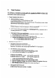
D, Tuning Procedures: The transformer is incorporated in the power supply box. To avoid any interference cased by other electronic appliances, the system should be posed by en independent power source. The power socket should adhere to safety standard and grounded. 1. Testing Transmitter Board (figure 1) a. Adjusting Modulation Frequency The modulation frequency is preset at the factory at 180Hz.
E. e. Slide Switch (inside the metal sealing box) This is preset at the factory: Swi ON SW1-2 OFF SW1-3 ON This setting is for modulation frequency of 160Hz and suitable for both RF labels and tags. H only had tags are to be used, SW1-1 should be positioned to OFF. the system is 10 operate under modulation frequency of 180Hz, please reset 10 the followings: SW1-1 ON or OFF SW-2 ON §Wi3 ON Note: After changes are made, please RESET for steamfitting again.
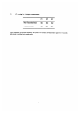
F. JP setting for Multiple connections: ties. Ip] PJP Main Transmitter Board i&2 1&2 1&2 Transmitter Board 1&2 2&3 2&3 After completion of multiple connection, the system will conduct self-examination again for 30 seconds after power is switched on as noted earlier.
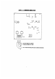
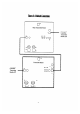
Figure 1 Transmitter Board (PCB) kal ono 5196 Power Supply, DC Output To Receiver Board, DC Input To a 2 Receiver Board, DC Input ( multiple connection)
o 74 Alma DSI DS2 DS3 GaN El ji 173 Oo GRIND 12.
Modifications not authorized by the manufacturer may void users authority to operate this device NOTE. This equipment has been tested and found to comply with limits for a Class B digital device, pursuant to Part 15 of the FCC Rules. These limits are designed to provide reasonable protection gamest harmful interference in a residential instillation.
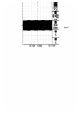
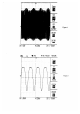
TTT TTT LARAREERSE2RERAM Figure 4 CH Bf Conn : Ri CHT TO “Was CHT 7 dy Figure 5 Co Hare Fou i .