
User's Manual


P3/P9
Two,theuseofcombination
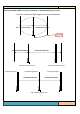
1. singlesendingandreceivingstate
Theareaofbothsidesoftheantennaismonitoredbyasingle
M6088G‐TR/M6090G‐TR/M6080G‐TR/M6088SG‐TR(withatransceiverfunction).
2.
Atwochargestate
FromaM6088G‐TR/M6090G‐TR/M6080G‐TR/M6088SG‐TRandtwoM6088G‐R/M60
90G‐R/M6080G‐R/M6088SG‐Risresponsibleformonitoringtheareabetweentworeceivingantennas.
3.Multimachineuse
IfyouneedtousemorethanoneM6088G‐TR/M6090G‐TR/M6080G‐TR/M6088SG‐TRtousetheneedto
synchronizewiththemachine.
Three.
Electricaldescription
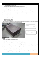
1.Powersupply
ACvoltage:220‐‐240VAC@50Hz
Powerinsurance:250V,0.63A
Maximumcurrent:100mA
Powerconsumption:<25W
Note: the power cord shall be used to ensure reliable grounding of the grounding line. The power box is not too far
awayfromthelaunchpad,theproposed10meterswithinthebest
Four.Mainfunctions
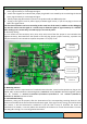
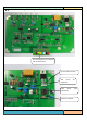
1.socket
ApoweroutletPOWER,CH‐R2,CH‐TR,CH‐R1
2.indicatorlight
.D1fortheredindicatorlight,whenthealarmisdisplayed.
.D2fortheblueworkindicator,toasecondforthecycleoftheflash.
.D3‐D9toreceivesignalstrengthindicator,D3isthehighest,D9isthelowest.Usuallyshowthereceiving
signalintensityof thetransmitantenna,iftheCH‐TR channelisshielded,can showthesignalintensityof
CH‐R2, ifCH‐R2 is shielded, can show the CH‐R1signal strength,which is related tothe choice of system
function.
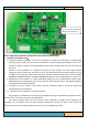
3.
Systemfunctionselection
JP4,fourJP5jumperfortheselectionofworkingmode.
1) wasthefirstjumperplugonshieldingCH‐TRchannelreceiver,isreceivingthechannelsignaldoesnot
causealarm,signalintensityisnotthroughthelights.
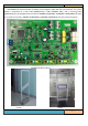
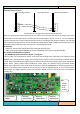
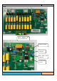
EG105powersupply
EG105 power supply output
interface (including synchronous
signal)forthemainboard