H Series——with Pan/Tilt of CMOS NC530 NC530W User Manual
http://www.wansview.com Index 1 INTRODUCTION ...........................................................................................................................4 2 FUNCTION AND FEATURES .....................................................................................................4 3 APPEARANCE AND INTERFACE.............................................................................................6 4 5 3.1 APPEARANCE .................................................................
http://www.wansview.com 7.3.2 Motion Detection Setting ...................................................................................................20 7.3.3 Alarm Mode Setting ...........................................................................................................21 7.3.4 Alarm Time Setting.............................................................................................................21 7.4 ADVANCE SETTING ................................................................
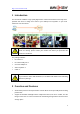
http://www.wansview.com 1 Introduction The IP Camera combines a high quality digital video camera with network connectivity and a powerful web server to bring clear video to your desktop from anywhere on your local network or over the Internet. Your IP Camera package should contain the following items, If any of the listed items are missing, please contact your reseller from where you purchased the camera for assistance.
http://www.wansview.com 9 VGA/QVGA/QQVGA resolution optional. User can change some specification according to their demands to satisfy his own visual prefer. 9 9 Support 3 kinds of video stream, suitable for Local, Internet and Cross-platform view. Built-in microphone, and also support to connect external audio capturing device (like MIC phone or sound pick-up) to capture the audio. External speaker can play the voice sent to the live scene, to achieve two-way intercom function. Audio support G.711 and G.
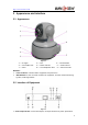
http://www.wansview.com 3 Appearance and interface 3.1 Appearance 1——IR Lights 4——Internal Mic Hole 7——Shell Figure 1 2——Lens 5——Power Indicator 8——Heat Dissipation Hole 3——Photovaristor 6——WIFI Indicator 9——SD Card Socket Remarks: ¾ Power Indicator: it will turn RED if equipment was powered on. ¾ WIFI Indicator: If there is a WIFI module in the equipment, and there is data transferring by WIFI, it will begin twinkle. 3.
http://www.wansview.com 2) WIFI Antenna Hole: Install the WIFI antenna. 3) RESET Button: Press the RESET button and hold on more than 5 seconds, the equipment will restart and recover to the factory default settings. The Pan/Tilt will move around for one circle and finally focus to the center. 4) RJ45 Ethernet Socket: RJ45 Ethernet socket is 10/100M self-adjust. The equipment can connect to all kinds of network equipments, such as hub, router, switch, etc.
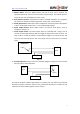
http://www.wansview.com 4 Network Connecting Figure 5 IP Camera can be connected with other PC through router, switch or hub to establish a network. Figure 5 shown connections. 4.1 Connection Instruction Before visit the IP Camera, you should firstly connect it to the Network, supply the power to it, and check if the light of RJ45 Socket is normal to make sure all of the communication links are fluency. The connection method likes as Figure 5.
http://www.wansview.com 2) The PC and IP Camera are in different LANs, but they are all connected to Internet. For the IP Camera-1 and PC-2 in Figure 5, if you want to visit IP Camera-1 by PC-2, you should firstly do the setting as 1) to make sure that you can visit IP Camera-1 through PC-1 and then do the setting of router-1 (do the port forwarding from the router). The PC-2’s visit application could be sent through router-1 to IP Camera-1.
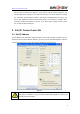
http://www.wansview.com IP Camera by default use fixed IP address 192.168.0.158 and fixed http port 80. If you don’t have this software, you could also press down the reset button (Figure 2) to go back the factory setting. Then you could use this defaulted IP address to visit the IP Camera. Setting Instruction: 9 Please carefully check the “Local PC information” on the top left corner which lists the PC configuration.
http://www.wansview.com Figure 8 After the ActiveX installation, click the “Video View” as Figure 7, then you will enter the video view home page as below Figure 9. Figure 9 5.2.1 Menu column There are 2 kinds of menu, one is main menu, the other is submenu. The main menu lies at the top of the interface, including View, Media, Network, Alarm, Advanced and System; Submenu lies on the left of the interface, and different main menu is in line with different submenu.
http://www.wansview.com 5.2.2 Video Displaying Area The video displaying area is correspond to the resolution, the higher the resolution is, larger the displaying area will be. If motion detection was set, when it has detected any movements of the certain area, it will show a pane to call user’s attention. Figure 10 is status column at the bottom of video displaying area. Figure 10 1) Displaying how many users are visiting this video.
http://www.wansview.com 5.2.5 Record Click “Record” button, which could record the video with audio and store it at the present path. When recording, there will be an indicated symbol in the status of video display area to show you it is recording. Click the “Record” button again, and then the record stops. 5.2.6 Playback Click “Playback” button, it will pop up a player which could play the video stored on your PC disk.
http://www.wansview.com 6 Visit IP Camera from WAN 6.1 Port forwarding Follow the “Visit IP Camera from LAN” steps; make sure PC-1 can visit IP Camera-1. In Figure 5, before the computers in WAN (PC-2, PC-3) can visit the IP Camera-1, must put the IP Camera -1 into WAN. You can set port forwarding on Router-1 to put IP Camera-1 into WAN. Open the Router Setting interface on PC-1.
http://www.wansview.com dynamic domain name server (DDNS). IP Camera-1 send IP configuration to DDNS every few time, DDNS can recognize the WAN IP address of the router-1 which connected with IP Camera-1. The WAN IP address can be searched on DDNS by domain name. Herein, domain name substitute the dynamic IP address. If the device can’t be visited by IP address, this domain name is also unavailable. 6.2.
http://www.wansview.com 7 Other Settings 7.1 Video Setting Page 7.1.1 Video Setting Figure 16 1) Power Line Frequency If the monitoring site adopting lighting elimination, user should set a corresponding frequency. If the two frequencies are different, the image will flick. There are two frequencies on the world, one is 50HZ, and the other is 60HZ. In China, adopt 50HZ. 2) First Stream Use H.
http://www.wansview.com Use H.264 code , support QVGA(320*240)、QQVGA(160*120), also can setting bit rate and Max frame rate . 4) JPEG Stream JPEG stream send JPEG picture, support the browser which don’t support H.264 code, like mobile phone. Also can use Http://ip:port/mobile.html to view JPEG stream. For more details, please refer to Chapter 8. 5) Parenthesis Options Through the setting, user can add the time and Camera name to the image. 7.1.
http://www.wansview.com 7.1.3 Image Setting Figure 18 1) 2) Color Adjustment: Drag the glide bar showed as above Figure 18, user can adjust the brightness, saturation, contrast, hue. Image Display Adjustment: There are “Flip” and “Mirror” two options, select it for the image display. 3) Night vision mode: If you choose “auto” mode, IR lights will be lighted on and shut off by the photoresistance. If you choose manual mode, you can light on and shut off the IR light manually.
http://www.wansview.com 1) LAN Setting: The default setting of this equipment is showed as above Figure 19, user can change it according to your network environment. 2) HTTP Port: The IP address Identity one IP camera in the network, you can run several programs on this equipment, and every program will transfer the data through some port, in fact data is transferred from one port to another. The port setting of this page is asking user choose which port to transfer the data for the web server. 7.2.
http://www.wansview.com Before using UPNP function, please make sure the router’s UPNP function has been triggered. Because there are so many different routers, and not all of them can support UPNP. Please test if the router work well with the equipment, if not, we would suggest you don’t enable this function. 3) WAN IP Test: Click the “Show” button, it will show you another new page displaying the WAN IP address when it is connected to the Internet. 7.3 Alarm Setting Page 7.3.
http://www.wansview.com trigger alarm. The motion detection setting page is showed in Figure 22. This equipment supports four areas settings. By ticking the options, on the screen, it will show you the area frame, and the areas are numbered. Using the mouse to drag the area frame, you can change the position of the frame, and to drag the right bottom corner of frame, you can change the size of frame. After setting is finished, click “Apply“ button, then the motion detection is enabled. 7.3.
http://www.wansview.com 7.4 Advance Setting 7.4.1 User Management There have three level of authority; they are admin/user/guest. Admin have the highest authority, it can do any change to the settings. User account only can operate the IP camera, can’t do changes to the settings, and please refers to Figure 26. Guest account only can watch the video, can’t do any operation to the IP camera, and please refers to Figure 27.
http://www.wansview.com Figure 27 7.4.
http://www.wansview.com 7.4.3 E-mail Setting Figure 29 In Figure 29, the blanks which have been filled with info should be filled. If any info is not filled right, the setting will fail. Before setting these parameters, please refer the settings of Outlook Express. 7.4.4 FTP Setting Figure 30 In order to use FTP function, user should apply username and password on the FTP server first. And please apply some storage, and the authority to write and create sub-category into it.
http://www.wansview.com 7.4.5 Alarm Server Setting Figure 31 Please confirm if you have connected to alarm server. The alarm message format as follow: GET /api/alarm.asp? username=username& userpwd=password& rea=alarm type (1=Motion Detection, 2 =Alarm from Alarm in port, 3 =Other Type)& io=0 Alarm server need develop by customer; user can extend other functions on this server, like SMS, MMS alarm, and mobile phone etc. 7.5 System Setting Page 7.5.
http://www.wansview.com display “Wireless LAN” connected by wireless Router. ¾ SD status will remind if SD card inserted and display the free capacity. Click “Browse” to view the contents in SD card and, “Format SD Card as fat32” to format SD Card and, “Unplug SD Card” to stop the work of SD Card. The device supports max 32G SD card. Please format the SD card to FAT32 before use the card on Camera. Please check if the SD Card matches the camera or not before purchase the SD Card. 7.5.
http://www.wansview.com little long, please wait patiently. If upgrading is finished, it will show you a message to remind you. Figure 34 7.5.4 System Log Checking Figure 35 7.5.
http://www.wansview.com 8 Advanced Application 8.1 Mobile phone Browsing After connect into network, you can view by mobile phone. Device will send MJEPG picture to mobile phone, you can setting the image resolution, which mention on Chapter 7.1.1. View way as below: 1) http://IP:Port/mobile.html, for example: http://58.61.54.177:1025/mobile.html http://test.3322.org:1025/mobile.html Smartphone (like iphone, windows mobile, symbian, black berry, Android etc.) can use this mode to visit.
http://www.wansview.com dialog box from Edit Menu. Click Advanced, select “custom..” in the Transport Setup. It pops up the Streaming Transport dialog box. Please select “HTTP” for transport protocol and “80” as port ID, and then click “ok”. Please be back to Transport Setup to change “Custom..” to “Auto”. Finally, click “ok” at the bottom. Please refer to the above Figure 38. Then you could view the video through Firefox or Safari now.
http://www.wansview.com Figure 39 For more information, pls. refer the <> in CD. 9 Technical Parameters Item Sub item Description Sensor 1/4" CMOS sensor Image Total of pixel 300k Capture Minimum illumination IR lights on,0 Lux Lens f=4.5mm, F=2.
http://www.wansview.com Other Protocol Other 802.
http://www.wansview.com 10 FCC STATEMENT 1. This device complies with Part 15 of the FCC Rules. Operation is subject to the following two conditions: (1) This device may not cause harmful interference. (2) This device must accept any interference received, including interference that may cause undesired operation. 2. Changes or modifications not expressly approved by the party responsible for compliance could void the user's authority to operate the equipment.