
User's Manual

www.SolidRFCanada.com 3
Installation
2
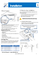
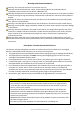
1.3 Set the outside antenna cable into the building
• Carefully arrange the cable along the building outside
and make sure don’t fold it or roll up;
• Fix the cable at each corner;
2.3 Connect the outside antenna’s connector to the “ANT2”
port of the booster;
2.4 Connect the inside antenna to the “ANT1” port;
Step 3: power on the booster
a. Plug the power adapter to the AC power;
b. Attach the cord of the adapter to the booster and switc
h on;
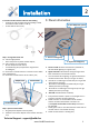
Step 2: arrange the inside unit
2.1 Choose right position
• 20cm away from any other metallic objects;
2.2 50cm away from any windows;
• Be sure away from heat source;
• In ventilate dry place, temperature range should
0~+50degree;
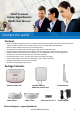
Outside antenna
Adapter cord
Power Switch
Technical Support: support@solidrf.ca
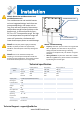
1. Power on LED(green)
3. Panel information
2. Signal level LED(green)
3. Alert LED(red or green)
1. Power on LED: whenever the booster is powered on,
this LED will be lighting on in green color;
a. If none of these LED is lighting: no signal received from
the base station tower. Here you can get no service;
b. One LED on: outside signal is weak and you can get 300
square feet up coverage;
c. Two LED on: outside signal is middle and you can get
1200 square feet up coverage;
d. Three LED on: outside signal is strong and you can get
3000 square feet up coverage;
2. Signal level LED: indicated how strong the signal have
been received from the outside antenna.
3. Alert LED: indicate booster condition;
a. Every time the booster is power on it will light on for a
second in red color and then switch off;
b. Stable red color on: the installation of the outside
antenna and the inside booster’s location is no
suitable(face to each other or too close) and need to
be relocated;
c. Stable green color on: the cable from the inside unite to
outside unite isn’t connected correctly;
d. Stable off: the booster is working well;