
Product Manual


4
2. Interface
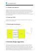
When the module is connected to the user mainboard, it mainly includes serial port interface, reset,
wake up, mode control, status output and power supply interface, etc. Figure 2-1 shows the
module pins.
Figure 2-1 Module pins
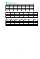
2.1 Module pin definition
Pin
Function
Port Type
Description
1
NSS
I
SPI chip selection
2
M0SI
I
SPI data input
3
MISO
O
SPI data output
4
SCK
I
SPI clock
5
NC
-
Serial port receiver (RX)
6
DIO3
I/O
Interrupt the I/O port
7
NC
Ground
8
DIO1
I/O
Interrupt the I/O port
9
3.3V
POWER
System power supply,
power supply range
1.8~3.6V
10
GND
POWER
Ground
11
C1
-
Reserved
12
C2
-
Reserved