
Product Manual


6
platform to the module.
2.2.4 Module status indicator
Module status indicator pin is the 13 busy pin. If the user sends serial port data to the module,
check the level status of the BUSY pin. The user can send serial port data to the module only when
the BUSY pin is high level (idle state). After the module receives user data, BUSY pins will be
lower, indicating that the module will carry out data communication. After the data
communication ends, the BUSY pin will be pulled up again, indicating that the user has completed
the data communication.
2.2.5 Interrupt GPIO
Interruption GPIO ports DIO1 and DIO3 are used for data transmission with internal chip, and
cannot be used as extended IO ports.
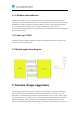
2.3 Module application diagram
3. Antenna design suggestions
Antenna design is directly related to the communication performance of the product. Different
types of antennas are selected for different terminals according to the antenna size, cost, and
performance. Common short-range antennas include PCB antenna, chip (ceramic) antenna, spring
antenna, whip antenna, etc. When selecting an antenna, the following most important parameters
should be considered: radiation variation in different directions around the antenna, antenna
efficiency, bandwidth required for antenna operation, and power to be provided to the antenna, etc.