Step 5: Here you can configure the NAT. If you are not an advanced user, the default settings are recommended and then click Next. Step 6: To configure the Default Gateway interface when using IPv6, select the interface that you want to configure with the WAN gateway address in Selected WAN Interface box. Then click Next.
Step 8: Here you can view your configurations. Click Apply/Save to save your settings if everything is correctly set. When the IPoE connection is successful, you can access the Internet. Bridging If you wish to initiate a dialup directly from your PC for Internet access or enjoy the entire Internet connection (instead of sharing it with others), you can select the Bridging and create a dialup program from your PC. Step 1: Click Advanced Setup > WAN Service and then click the Add button.
default. And click Next. Step 4: Here you can view your configurations. Click Apply/Save to save your settings if everything is correctly set. After the bridging connection is successful, initiate a dialup directly from your PC for Internet access.
.2.3 LAN Setup Here you can configure the LAN IP Address and subnet mask. This IP address is to be used to access the device’s settings through a web browser. Be sure to make a note of any changes you apply to this page. This part includes the following information: IPv4 IPv6 Autoconfig IPv4 IP Address: The device's LAN IP address. The default setting is 192.168.1.1. Subnet Mask: The LAN subnet mask of the device.
Leased Time: The lease time is a time length that the IP address is assigned to each device before it is refreshed. Static IP Lease List: Displays a list of devices with reserved static IP addresses. Add Entries: Click to add a static IP lease entry. A maximum 32 entries can be configured. Remove Entries: Click to remove a static IP lease entry.
IPv6 LAN Applications Enable DHCPv6 Server:Check to enable the DHCPv6 Server. Stateless: If selected, IPv6 clients will generate IPv6 addresses automatically based on the Prefix Delegation's IPv6 prefix and their own MAC addresses. Stateful: Stateful DHCPv6 is supported based on the assumption of prefix length less than 64. Select this option and configure the start/end interface ID and leased time. The router will automatically assign IPv6 addresses to IPv6 clients.
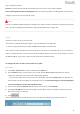
4.2.4 NAT This section explains the following: • Virtual Server • Port Triggering • DMZ Host • UPnP Virtual Server The Virtual Server is useful for web servers, ftp servers, e-mail servers, gaming and other specialized Internet applications. When you enable the Virtual Server, the communication requests from the Internet to your router’s WAN port will be forwarded to the specified LAN IP address. To enter the virtual server screen, click NAT > Virtual Server and then click the Add button to add rules.
ports at the Internet interface. Protocol: Select the protocol from the Protocol drop-down list. If you are unsure, select TCP/UDP. Internal Starting Port and Internal Ending Port: These are the starting number and ending number for the ports of a computer on the router’s local area network (LAN).
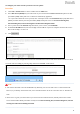
To configure your router to make your local web server public: Procedure 1. Click NAT > Virtual Server to enter it and then click the Add button. 2. Select Web Server (HTTP) that you wish to host on your network from the Select a Service drop-down list. The port number (8080) used by this service will then be automatically populated.
Port Triggering Some applications such as games, video conferencing, remote access applications and others require that specific ports in the Router's firewall be opened for access by the applications. Port Trigger dynamically opens up the 'Open Ports' in the firewall when an application on the LAN initiates a TCP/UDP connection to a remote party using the 'Triggering Ports'.
automatically opened by the built-in firewall when connections initiated by an application are established. DMZ Host The default DMZ (De-Militarized Zone) host feature is helpful when you are using some online games and videoconferencing applications that are not compatible with NAT (Network Address Translation). DMZ Host IP Address: The IP Address of the device for which the router’s firewall will be disabled. Be sure to assign a static IP Address to that device.
Enable UPnP: Check/uncheck to enable/disable the UPnP feature. _________________________________________________________________________________________________ NOTE UPnP is activated only when there is a live WAN service with NAT enabled. _________________________________________________________________________________________________ 4.2.
This screen allows you to create a filter rule to identify outgoing IP traffic by specifying a new filter name and at least one condition below. All of the specified conditions in this filter rule must be satisfied for the rule to take effect. Click to save and activate the filter. Filter Name: Enter a descriptive filtering name. IP Version: Support IPv4. Protocol: TCP/UDP, TCP, UDP and ICMP are available for your option.
Click Add to enter the following screen: This screen allows you to create a filter rule to identify incoming IP traffic by specifying a new filter name and at least one condition below. All of the specified conditions in this filter rule must be satisfied for the rule to take effect. Click to save and activate the filter. IP Version: Select IP version. Protocol: TCP/UDP, TCP, UDP and ICMP are available for your option.
_________________________________________________________________________________________________ Warning! Changing from one policy to another of an interface will cause all defined rules for that interface to be REMOVED AUTOMATICALLY! You will need to create new rules for the new policy.
• Time Restriction • URL Filter Time Restriction Click Parental Control > Time Restriction > Add to enter the following screen. Here you can add time of day restriction that an attached LAN device can access the Internet. The Browser's MAC Address automatically displays the MAC address of the LAN device where the browser is running. To restrict other LAN device, check the "Other MAC Address" option and enter its MAC address. User Name: Enter a user name.
Select the URL List Type (Exclude or Include) first and then click Add to enter the screen below for configuring the list entries. URL Address: Enter a specific URL or a key word of domain name in this field. Click to apply and save the settings. _________________________________________________________________________________________________ NOTE If you have accessed the URL before you include it in a URL filter rule, you must reboot the router and erase it from your PC to activate this URL filter rule.
2. Then type ipconfig /flushdns and hit Enter on the keyboard. _________________________________________________________________________________________________ 4.2.7 Bandwidth Control When multiple devices each of which requests a different bandwidth attach to the modem router, to ensure the attached devices obtaining a fair bandwidth and getting a fluent Internet experience, set a bandwidth control rule. Check Enable Bandwidth Control to enable this feature.
Description: Name the bandwidth control rule as you like. IP Address Range: Type the IP address range of target hosts. Follow the example If you want to set one host, follow the example . . Max Upstream Speed (Kbps): Set the upstream speed as your actual bandwidth need. Max Downstream Speed (Kbps): Set the downstream speed as your actual bandwidth need. Status: Enable or Disable.
Available Routed WAN Interfaces: Displays the available routed WAN interfaces. Select a WAN interface and click the button to add it to the Selected Default Gateway Interfaces box. Apply/Save: Click to save and activate your settings. Static Route Static routes provide additional routing information to your router. Typically, you do not need to add static routes. However, when there are several routers in the network, you may want to set up static routing.
router. Metric: Enter a number in the Metric field. This stands for the number of routers between your network and the destination. Apply /Save: Click to apply and save your settings. _________________________________________________________________________________________________ NOTE 1. Destination IP address cannot be on the same IP segment as WAN or LAN segment as the router. 2.
② Check the Select DNS Server Interface from available WAN interfaces option if the device gets a DNS address automatically from an upstream device. Or select the Use the following Static DNS IP address option and enter static DNS server address provided by your ISP. ③ Click Apply/Save at the bottom of the page. For IPv6 ① Click Advanced Setup > DNS > DNS Server, and enter the screen below.
addresses are not routed on the Internet. Click Advanced Setup > DNS > Dynamic DNS to enter the Dynamic DNS screen. Click to configure the DDNS settings. D-DNS Provider: Select your DDNS service provider from the drop-down menu. Hostname: Enter the DDNS domain name registered with your DDNS service provider. Interface: Specify a WAN connection interface. Username: Enter the DDNS user name registered with your DDNS service provider.
② Enter the hostname. Here is “tenda.dyndns.org” for example. ③ Specify a WAN connection interface. DynDNS Settings ④ Enter your DynDNS username. Here is “tenda” for example. ⑤ Enter the password of DynDNS account. Here is “123456789” for example. ⑥ Click to save your configuration. 4.2.10 DSL This screen provides multiple ASDL modulation modes to meet diversified environments. You can also select phone line pair and Capability.
Check the checkbox next to a modulation to enable it and then click . Advanced Settings: Click it to enter the Advanced Settings screen as below. Here you can select the test mode and tone. _________________________________________________________________________________________________ TIP If you are unsure about the DSL parameters, please apply the factory default settings. Wrong configurations may fail your Internet access.
Click and then uplug your USB device. Removing directly may damage your USB storage device. User Account Accessing the USB storage device requires an account. You can click to use the default account or you can customize a new one. Pay attention to that your computer system will record the account you used at the first time. Application: How to access the USB storage device attached to the modem router? Step 1: Plug USB storage device.
to save and apply. Step 3: Access the USB storage device from a computer. Click +R on the keyboard to pop up the Run dialog, and type \\192.168.1.1 in the blank field. Click OK. Step 4: Access the USB storage device with the account “samba”. Double click , and enter your account “samba” and password to finish the credentials. Then, click OK.
Access successfully! 4.2.12 Interface Grouping Interface Grouping supports multiple ports to PVC and bridging groups. Each group will perform as an independent network. To support this feature, you must create mapping groups with appropriate LAN and WAN interfaces using the Add button. The Remove button will remove the grouping and add the ungrouped interfaces to the Default group.
Click Add to enter the screen below: Group Name: Define a name for group. WAN Interface used in the grouping: WAN connection to which the interface grouping rules apply. Available LAN Interfaces: LAN interfaces which are available for interface grouping. Grouped LAN Interfaces: LAN interfaces which are classed into the specified WAN connection. To create a new interface group: ① Enter the Group name and the group name must be unique.
4.2.13 IP Tunnel This section explains the following information: • IPv6inIPv4 • IPv4inIPv6 IPv6inIPv4 Click IPv6inIPv4 and Add to enter the following screen: Tunnel Name: Specify the name of the tunnel. Mechanism: Currently, only 6RD configuration is supported. Associated WAN Interface: Specify the WAN interface of the tunnel. Associated LAN Interface: Specify the LAN interface of the tunnel.
IPv4inIPv6 Click IPv4inIPv6 and Add to enter the following screen: Tunnel Name: Specify the name of the tunnel. Mechanism: Currently, only DS-Lite configuration is supported. Associated WAN Interface: Specify the WAN interface of the tunnel. Associated LAN Interface: Specify the LAN interface of the tunnel. Manual: If you select Manual, enter the AFTR information also: Automatic: If Automatic is selected, no configurations are required.
certificates can be stored. To generate a certificate signing request: ① Click the Create Certificate Request button to enter the page below. ② Specify the Common Name, Organization Name and State/Province Name ③ Enter the 2-letter Country Code for the certificate. ④ Click Apply to apply your settings. To Import certificate: ① Click the Import Certificate button on the local certificates page to enter the page below.
② Enter the certificate name. ③ Paste the certificate content and private key. ④ Click Apply to apply your settings. Trusted CA (Certificate Authority) Certificates Here you can add, view or remove CA certificates. CA certificates are used by you to verify peers' certificates. Maximum 4 certificates can be stored.
To Import certificate: ① Click the Import Certificate button to enter the page below. ② Enter the certificate name. ③ Paste the certificate content. ④ Click Apply to apply your settings. 4.2.15 Multicast Here you can configure the multicast feature. To configure IGMP for IPv4 ① Check the LAN to LAN (Intra LAN) Multicast Enable box. ② Check the Membership Join Immediate (IPTV) box. This is only required for IPTV. ③ Keep other options unchanged from factory defaults if you are not an advanced user.
To configure IGMP for IPv6 ① Check the LAN to LAN (Intra LAN) Multicast Enable box. ② Keep other options unchanged from factory defaults if you are not an advanced user. This is strongly recommended.
4.2.16 IPTV If you check the Enable IPTV checkbox, you must choose a layer2 interface, and then configure the PVC info (ATM), or VLAN info (ETH). Click to save it. Enable IPTV: Check to enable the IPTV service, or disable it. IPTV configuration for DSL Internet Access user: ① Enable IPTV. ② Select Layer2 interface: ATM Interface. ③ Configure an available VPI/VCI value which should be provided by your ISP. ④ Click . IPTV configuration for Ethernet Internet Access user: ① Enable IPTV.
After successful IPTV configurations, Port 4/iTV on the back panel of the device can only be an IPTV port. _________________________________________________________________________________________________ TIP For tagged service, enter valid 802.1P Priority and 802.1Q VLAN ID. For untagged service, set -1 to both 802.1P Priority and 802.1Q VLAN ID. _________________________________________________________________________________________________ 4.
Enable Wireless: check/uncheck to enable/disable the wireless feature. Hide Access Point (Hide SSID): This option allows you to have your network names (SSID) publicly broadcast. If you choose to enable it, the SSID will be hidden. SSID: This is the public name of your WiFi. BSSID: Display the MAC address of the wireless network. Country: Select your country.
WPS Setup Wi-Fi Protected Setup makes it easy for home users who know little of wireless security to establish a home network, as well as to add new devices to an existing network without entering long passphrases or configuring complicated settings. Enable WPS: This is WPS ON/OFF turn. Click it to enable or disable WPS. WPS is disabled by default. Device PIN: This is PIN code of the modem router for WPS PIN mode. Enter SAT PIN: “SAT” means the remote wireless client requiring a connection.
Manual Setup AP You can set the network authentication method, selecting data encryption, specify whether a network key is required to authenticate to this wireless network and specify the encryption strength. Click when done. Network Authentication: Select Open, Shared, WPA-PSK, WPA2-PSK or Mixed WPA/ WPA2-PSK from the drop-down list to encrypt your wireless network. Depending on the type of network authentication you select, you will be prompted to enter corresponding settings.
4.3.3 MAC Filter The MAC-based Wireless Access Control feature can be used to allow or disallow clients to connect to your wireless network. MAC Restrict Mode: Disabled, Allow and Deny Allow: Only allow PCs at specified MAC addresses (in the list) to connect to your wireless network. Deny: Block only PCs at specified MAC addresses from connecting to your wireless network. Disable: Disable this feature. Add: Click it to add a MAC address.
③ Enter 00:1A:3D:9C:BB:23 in the MAC address box as shown in the figure below, and click Set up successfully! ________________________________________________________________________________________________ NOTE If “Allow” mode is activated with no MAC address being limited, WPS feature will be disabled. Go to Wireless > Security to check WPS status). ________________________________________________________________________________________________ 4.3.
AP Mode: You can select Wireless Bridge (also known as Wireless Distribution System) to disable access point functionality. Selecting Access Point enables access point functionality. Wireless bridge functionality will still be available and wireless stations will be able to associate to the AP. Bridge Action: There are three options available: Enabled, Enabled (Scan) and Disabled. Disabled mode means disabling the wireless bridge function.
Before you get started: ① View and note down the security settings of Router 1: wireless name (SSID), channel, security mode, MAC address and wireless key. a) Click Advanced > Wireless > Basic to check the SSID, MAC address (BSSID) and Channel. SSID: Tenda_112252 BSSID: 00:90:4C:11:22:53 Channel: 6 b) Click Advanced > Wireless > Security to check security mode and wireless key.
WPS: Disable Security Mode: WPA2-PSK / AES Wireless Key: 12345678 ② View the LAN settings of Router 1. Click Advanced > Advanced Setup > LAN to check LAN IP address and Subnet Mask, and verify that the DHCP Server is enabled. LAN IP Address: 192.168.1.1; Subnet Mask: 255.255.255.
After you prepare two steps above, do as follows: Configure Router 2: ① ② Set the LAN IP address of Router 2 to a different IP address yet on the same segment as Router 1. Click Advanced > Advanced Setup > LAN to change the LAN IP address into 192.168.1.10. Disable your DHCP server. Click Advanced > Wireless > Basic to check the SSID and Channel. They should be the same as Router 1’s. If not, correct them manually. Click Apply/Save to save your settings.
Enter the MAC address of Router 1 which you have noted down (00:90:4C:11:22:53). Then click Apply/Save to save the settings. b. If you select Enable(Scan) in Bridge Action field. Select the SSID of Router 1 (Tenda_112252) in Remote Bridges MAC Address field. If you cannot find the SSID on the list, click Refresh to refresh the list. Then click Apply/Save to save your settings. Wireless Bridge Two ways to bridge Router 1 by using Wireless Bridge: a.
b. If you select Enable(Scan) in Bridge Action field: Select the SSID of Router 1 (Tenda_112252) in Remote Bridges MAC Address field. If you cannot find the SSID on the list, click Refresh to refresh the list. Then click Apply/Save to save your settings. After you fininsh the settings on Router 2 above, do as follows: Configure Router 1: ① Click Advanced > Wireless > Wireless Bridge. ② Select Access Point in AP Mode field.
Then click Apply/Save to save the settings. b. If you select Enable(Scan) in Bridge Action field: Select the SSID of Router 2 (Tenda_112252) in Remote Bridges MAC Address field. If you cannot find the SSID on the list, click Refresh to refresh the list. Then click Apply/Save to save your settings. The configuration is finished. Then the devices can connect Router 2 wirelessly or via Ethernet cables.
The configuration is finished. Then the devices can only connect Router 2 via Ethernet cables. NOTE The WDS feature (also known as Wireless Bridge) can only be implemented between 2 WDS-capable wireless devices. Plus, SSID, channel, security settings and security key must be exactly the same on both such devices. 4.3.5 Station Info This page shows authenticated wireless stations and their status. 4.
4.4.1 Diagnostics The device is capable of testing the connection to your DSL service provider, the connection to your Internet service provider and the connection to your local network. If a test displays a fail status, click “Rerun Diagnostic Tests” at the bottom of this page to make sure the fail status is consistent. If the test continues to fail, click “Help” and follow the troubleshooting procedures.
4.5 Management This section explains the following information: • Settings • System Logs • SNMP Agent • TR-069 Client • Internet Time • Access Control • Update Software • Reboot 4.5.1 Settings This section explains the following information: • Backup • Restore Backup • Restore Default Backup Here you can save a copy of your device’s configurations to your computer. Once you have configured the device, you can save these settings to a configuration file on your local hard drive.
Restore Backup Here you can restore the configurations of the modem router from a file saved on your PC. Restore Default Under some circumstances (for example, join a different network or unfortunately forgetting the login password), you may need to remove the existing configuration and restore the factory default settings. 4.5.2 System Logs The System Log dialog allows you to view the system log and configure the system log options.
To configure the system log, click Configure System Log. Log: If Enable is selected, the system will begin to log all the selected events. Log Level: Set the log level. All events above or equal to the selected level will be logged. Display Level: Set the log display level. All logged events above or equal to the selected level will be displayed. Apply/Save: click to apply and save the system log settings.
SNMP Agent:Select “Enable” to activate the SNMP Agent feature or “Disable” to deactivate it. Read Community: Specify a Read Community string. The default is public. Set Community: Specify a Set Community string. The default is private. System Name: Specify a descriptive system name. System Location: Specify a system location. System Contact: Specify a system contact. Trap Manager IP: Specify the IP address of the Trap Manager. 4.5.
Inform: Select Enable/Disable to enable/disable the TR-069 Client function. By default, it is disabled. Inform Interval: Specify the inform interval. ACS URL: Enter the ACS (Auto-Configuration Server) URL address. ACS User Name: Enter the ACS (Auto-Configuration Server) user name. ACS Password: Enter the ACS (Auto-Configuration Server) password. WAN Interface used by TR-069 client: Select the WAN interface used by the TR-069 client from the drop-down list.
4.5.6 Access Control This section explains the following information: • Password • AccessControl - Service Password Access to your broadband router is controlled through two user accounts: admin and support. Admin has unrestricted access to change and view configuration of your Broadband Router. Support is used to allow a professional technician to access your Broadband Router for maintenance and to run diagnostics. User Name: Enter the user name of up to 16 characters. The default is “admin”.
Access Control - Service Here you can manage the device either from LAN or WAN side using HTTP, ICMP, TELNET, SNMP, FTP, TFTP and HTTPS. _________________________________________________________________________________________________ NOTE If you are not an advanced user, it is recommended to keep the default settings. ________________________________________________________________________________________________ 4.5.
This modem router supports three types to update firmware. Type 1: General Update To update software, do as follows: ① Obtain an updated software image file from our website: www.tendacn.com.
② Click the "Browse" button to locate the firmware file. ③ Click to start updating. Type 2: Updating Via FTP Server Updating via FTP server is supported. Make sure there is an available FTP server. ① Type the FTP Server IP address, like the right figure ② Type the port the FTP server used. ③ Type the user name and password to access the FTP server. ④ Copy the name of the firmware. ⑤ Click to start updating. Type 3: Updating Via TFTP Server Updating via TFTP server is supported.
NOTE The update process will cost 2 minutes, and the device will reboot. 4.5.8 Reboot Click the Reboot button to reboot the router.
Appendix 1 Applications Application 1: How to change SSID and wireless password? ① Go to Wireless > Basic interface. ② Specify a SSID as you like, like Tenda_myhome. ③ Click Apply/Save to save the settings. ④ Go to Wireless > Security interface. ⑤ Choose a network authentication (WPA2-PSK is recommended) and set a passphrase. ⑥ Click Apply/Save to save the settings.
Application 2: How to reset the modem router? The device supports two methods to reset to factory defaults. Note that after you reset the device, you should reconfigure it for Internet service. Method 1: WPS/RST button Press the WPS/RST button on the back of the modem router for about 8 seconds to reset it to factory defaults. Method 2: Restore Default Settings from User Interface ① Go to Management > Settings > Restore Default to enter the interface below. ② Click icon to start resetting.
Appendix 2 Configure Your PC This part is just for your references when your computer connecting to the modem router cannot get an IP address. Screens to configure TCP/IP properties in other Operating Systems are similar to those below. Windows 8 1. Right click the icon or on the bottom right corner of your desktop. TIP: If you cannot find the icon or , go to Control Panel and find Network and Internet. 2. Click Open Network and Sharing Center. 3. Click Ethernet > Properties.
4. Find and double click Internet Protocol Version 4(TCP/IPv4). 5. Select Obtain an IP address automatically and Obtain DNS server address automatically and click OK. 6. Click OK on the Ethernet Properties window (see Step 4 for the screenshot).
Windows 7 1. Click the icon on the bottom right corner of your desktop. 2. Click Open Network and Sharing Center. 3. Click Local Area Connection > Properties. 4. Find and double click Internet Protocol Version 4(TCP/IPv4).
5. Select Obtain an IP address automatically and Obtain DNS server address automatically and click OK. 6. Click OK on the Local Area Connection Properties window (see Step 4 for the screenshot).
MAC 1. Click on the Apple icon from the top-left corner and select System Preferences. 2. Click Network. 3. Click on Ethernet. 4. Select Using DHCP. 5. Click Apply.
Appendix 3 Join Your Wireless Network Windows 8 1. Click the icon on the bottom right corner of your desktop. TIP: 1. If you cannot find the icon , please move your mouse to the top right corner of your desktop, select Settings > Control Panel > Network and Internet > Network and Sharing Center > Change adapter settings, right click Wi-Fi and select Connect/Disconnect. 2. If you cannot find your wireless network from the list, ensure the Airplane Mode is not enabled on your PC. 2.
Windows 7 1. Click the icon on the bottom right corner of your desktop. 2. Double click your SSID (wireless network name) and then follow onscreen instructions. 3. When your SSID (wireless network name) displays Connected as shown below, you’ve connected to it for Internet access successfully.
MAC 1. Click > System Preferences. 2. Select Network from Internet & Network. 3. Click WiFi. 4. Turn WiFi on. 5. Click No network selected. 6. Select the wireless network name of your router. 7. Enter the wireless password and click Join.
iPhone/iPad 1. Scroll screen to find the Settings icon and click it. 2. Click WiFi, and turn on WiFi. 3. Find the name of the wireless network you wish to connect, and click it. 4. Enter the wireless password and click Join.
Appendix 4 FAQs 1. What information should I have to access the Internet via the DSL uplink? If you have DSL broadband service, you might need the following information to set up your modem router.
Appendix 5 VPI/VCI List The following table lists common ISPs and their VPI and VCI numbers. If you cannot locate your ISP and their VPI and VCI information here, ask your ISP to provide it.
Country ISP VPI VCI Brazil Telmar 0 33 PPPoE LLC Brazil South Region 1 32 PPPoE LLC Canada Primus Canada 0 35 PPPoE LLC Canada Rogers Canada (1) 0 35 PPPoE LLC Canada Rogers Canada (2) 8 35 1483 Bridged IP LLC Canada Rogers Canada (3) 0 35 1484 Bridged IP LLC Canada BellSouth(1) Canada 8 35 PPPoE LLC Canada BellSouth(2) Canada 0 35 PPPoE LLC Canada Sprint (1) Canada 0 35 PPPoA LLC Canada Sprint (2) Canada 8 35 PPPoE LLC Canada Verizon (1) Canada 0 35
Country ISP VPI VCI Hungary Encapsulation Sci-Network 0 35 PPPoE LLC Iceland Islandssimi 0 35 PPPoA VC-MUX Iceland Siminn 8 48 PPPoA VC-MUX India Airtel 1 32 1483 Bridged IP LLC India BSNL 0 35 1483 Bridged IP LLC India MTNL 0 35 1483 Bridged IP LLC 0 35 PPPOE LLC RELIANCE India COMMUNICATION India TATA INDICOM 0 32 PPPOE LLC India CONNECT 1 32 PPPOE LLC 8 81 PPPoE LLC 0 35 PPPOE LLC Indonesia Speedy Telkomnet [Shatel] Iran Aria-Rasaneh-Tadbir Iran Asia
Country ISP VPI VCI Encapsulation Israel(1) 8 48 PPPoA VC-MUX Italy 8 35 1483 Bridged IP LLC Italy 8 35 PPPoA VC-MUX Jamaica (1) 8 35 PPPoA VC-MUX Jamaica (2) 0 35 PPPoA VC-MUX Jamaica (3) 8 35 1483 Bridged IP LLC SNAP Jamaica (4) 0 35 1483 Bridged IP LLC SNAP 0 40 LLC/SNAP Bridging Kazakhstan 0 33 PPPoA VC-MUX kuwait unitednetwork 0 33 1483 Bridged IP LLC 0 35 PPPOE LLC 0 35 PPPoE LLC Kazakhtelecom Kazakhstan «Megaline» Malaysia Streamyx Malaysia Mexico
Country VPI VCI Philippines(1) 0 35 1483 Bridged IP LLC Philippines(2) 0 100 1483 Bridged IP LLC Portugal 0 35 PPPoE LLC 0 35 PPPoA LLC 0 35 1483 Bridged IP LLC Puerto Rico ISP Coqui.
Country ISP VPI VCI Spain Wanadoo (2) 8 32 PPPoE LLC Spain Terra 8 32 1483 Bridged IP LLC/SNAP Spain Terra 8 32 1483 Bridged IP LLC/SNAP Spain Uni2 1 33 1483 Bridged IP VC-MUX Spain Orange 8 35 1483 Bridged IP VC-MUX Spain Orange 20 Megas 8 35 LLC-BRIDGING Spain Orange 8 32 1483 Bridged IP LLC/SNAP Spain Ya.com 8 32 1483 Bridged IP VC - MUX Spain Ya.
Country ISP VPI VCI United States Encapsulation Ameritech 8 35 PPPoA LLC United States AT&T (1) 0 35 PPPoE LLC United States AT&T (2) 8 35 1483 Bridged IP LLC United States AT&T (3) 0 35 1483 Bridged IP LLC United States August.net (1) 0 35 1483 Bridged IP LLC United States August.net (2) 8 35 1483 Bridged IP LLC United States BellSouth 8 35 PPPoE LLC United States Casstle.
Country ISP VPI VCI United States Encapsulation Sonic 0 35 1484 Bridged IP LLC United States SouthWestern Bell 0 35 1483 Bridged IP LLC United States Sprint (1) 0 35 PPPoALLC United States Sprint (2) 8 35 PPPoE LLC United States Sprint Territory 0 35 PPPoE LLC 0 34 1483 Bridged LLC Snap 0 32 PPPoE LLC 0 32 PPPoA LLC SureWest United States Communications(1) SureWest United States Communications(2) SureWest United States Communications(3) United States Toast.
Country ISP VPI VCI Australia Telstra 8 35 PPPoA LLC Australia GoldenIT 8 35 _PPPOA_VCMUX Australia Telstra Bigpond 8 35 PPPOE_LLC Australia OptusNET 8 35 PPPOE_VCMUX Australia AAPT 8 35 PPPOE_VCMUX Australia ADSL Direct 8 35 PPPOE_LLC Australia Ausie Broadband 8 35 PPPOE_LLC 8 35 PPPOA_VCMUX Australia Australia On Line Encapsulation Australia Connexus 8 35 PPPOE_LLC Australia Dodo 8 35 PPPOE_LLC Australia Gotalk 8 35 PPPOE_VCMUX Australia Interno
Country ISP VPI VCI Canada Rogers Canada (3) 0 35 1484 Bridged IP LLC Canada BellSouth(1) Canada 8 35 PPPoE LLC Canada BellSouth(2) Canada 0 35 PPPoE LLC Canada Sprint (1) Canada 0 35 PPPoA LLC Canada Sprint (2) Canada 8 35 PPPoE LLC Canada Verizon (1) Canada 0 35 PPPoE LLC Canada Verizon (2) Canada 0 35 1483 Bridged IP LLC Colombia EMCALI 0 33 PPPoA VC-MUX Columbia ETB 0 33 PPPoE LLC Costa Rica ICE 1 50 1483 Routed IP LLC 8 48 1483 Bridged IP LLC 0
Country ISP India MTNL VPI VCI Encapsulation 0 35 1483 Bridged IP LLC 0 35 PPPOE LLC RELIANCE India COMMUNICATION India TATA INDICOM 0 32 PPPOE LLC India CONNECT 1 32 PPPOE LLC 8 81 PPPoE LLC 0 35 PPPOE LLC Indonesia Speedy Telkomnet [Shatel] Iran Aria-Rasaneh-Tadbir Iran Asia-Tech 0 35 PPPOE LLC Iran Pars-Online (Tehran) 0 35 PPPOE LLC Iran Pars-Online (Provinces) 0 59 PPPOE LLC 0 35 PPPOE LLC [Saba-Net] Iran Neda-Gostar-Saba Iran Pishgaman-Tose 0 35 PPPOE
Country ISP VPI VCI Encapsulation Jamaica (3) 8 35 1483 Bridged IP LLC SNAP Jamaica (4) 0 35 1483 Bridged IP LLC SNAP 0 40 LLC/SNAP Bridging Kazakhstan 0 33 PPPoA VC-MUX kuwait unitednetwork 0 33 1483 Bridged IP LLC 0 35 PPPOE LLC 0 35 PPPoE LLC Kazakhtelecom Kazakhstan «Megaline» Malaysia Streamyx Malaysia Mexico Telmex (1) 8 81 PPPoE LLC Mexico Telmex (2) 8 35 PPPoE LLC Mexico Telmex (3) 0 81 PPPoE LLC Mexico Telmex (4) 0 35 PPPoE LLC IAM 8 35 PPPOE
Country ISP VPI VCI Russia Encapsulation Rostel 0 35 PPPoE LLC Russia Port telecom 0 35 PPPoE LLC Russia VNTC 8 35 PPPoE LLC Saudi Arabia (1) 0 33 PPPoE LLC Saudi Arabia (2) 0 35 PPPoE LLC Saudi Arabia (3) 0 33 1483 Bridged IP LLC Saudi Arabia (4) 0 33 1483 Routed IP LLC Saudi Arabia (5) 0 35 1483 Bridged IP LLC Saudi Arabia (6) 0 35 1483 Routed IP LLC 1483 Bridged IP VC-MUX Spain Arrakis 0 35 Spain Auna 8 35 1483 Bridged IP VC-MUX Spain Comunitel 0 33
Country ISP VPI VCI Spain Orange 20 Megas 8 35 LLC-BRIDGING Spain Orange 8 32 1483 Bridged IP LLC/SNAP Spain Ya.com 8 32 1483 Bridged IP VC - MUX Spain Ya.
Country ISP United States August.net (2) VPI VCI Encapsulation 8 35 1483 Bridged IP LLC United States BellSouth 8 35 PPPoE LLC United States Casstle.Net 0 96 1483 Bridged IP LLC United States CenturyTel (1) 8 35 PPPoE LLC United States CenturyTel (2) 8 35 1483 Bridged IP LLC United States Coqui.
Country ISP VPI VCI Encapsulation 0 34 1483 Bridged LLC Snap 0 32 PPPoE LLC 0 32 PPPoA LLC 0 35 PPPoE LLC SureWest United States Communications(1) SureWest United States Communications(2) SureWest United States Communications(3) United States Toast.
Appendix 6 Regulatory Compliance Information CE Mark Warning This is a Class B product. In a domestic environment, this product may cause radio interference, in which case the user may be required to take adequate measures. NOTE: (1) The manufacturer is not responsible for any radio or TV interference caused by unauthorized modifications to this equipment. (2) To avoid unnecessary radiation interference, it is recommended to use a shielded RJ45 cable.