Contents Contents .................................................................................................................................. 2 Introduction ............................................................................................................................. 2 Using This Manual ................................................................................................................... 2 Warning ............................................................................
Warning USING THIS SYSTEM AT EXCESSIVE VOLUMES CAN CAUSE PERMANENT HEARING DAMAGE. ALWAYS USE A VOLUME LEVEL AS LOW AS POSSIBLE.
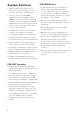
System Features • 100 selectable UHF frequencies for interference-free performance. (Up to 8 systems can operate simultaneously). PEM-1000R Receiver • Portable bodypack receiver features a power switch switchable with built-in volume output level control, select button for choosing one of 100 UHF channels, LCD channel display, stereo/mono, Signal/ Low Battery LED indicator.
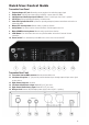
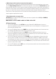
Quick User Control Guide Transmitter Front Panel 1. 2. 3. 4. 5. Earphone Output 1/4” jack: Connecting stereo earphones for monitoring output signal Volume Knob: Adjusting the volume clock-wise (MAX), counter clock-wise (MIN) Left/Right Source Audio Input Level LCD tree: Indicates if audio input source level is optional LCD display: Displaying Channel/Frequency, and other status Infrared Receptor/Sender LED: Synchronizes operatingnfrequency between transmitter and receiver as selected by either 6.
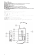
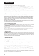
Bodypack Receiver 17. 18. 19. 20. 21. 22. 23. 24. 25. 26. 27. 28. 29. 30. 31 . 6 Power and Volume Control: Combo power ON/OFF switch and earphones volume adjust Earphone Out: 1/8” (3.
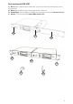
Rack-mounting the PEM-1000T 32. RKT-11: Optional rackmount kit for rackmounting a single unit. Includes front antenna mount, jack and connecting cable. 33. RKT-21: Optional rackmount kit for rackmounting two units side-by-side. 34. AC/DC Adapter: DC-12V/1000mA (110-240VAC, auto select), plugs into transmitter DC Input Jack (16) 35.
Operation PEM-1000T Transmitter 1. Rack-mounting the transmitter The PEM-1000T requires no installation and can be used on any flat surface. However, in some applications rack mounting is preferred. There are 2 options available for rack-mounting the PEM-1000T transmitter: singly or side-by-side with another PEM-1000T transmitter.
6. Monitoring on audio signal and connection with earphones The sound technician can monitor the signal being transmitted with a pair of wired headphones via the stereo 1/4” TRS Earphone Output Jack (1). The volume can be adjusted as desired with the Volume Knob (2). Both the left and right channels of a stereo signal are adjusted simultaneously by this control in the same manner.
PEM-1000R Receiver 1. Using the battery and the battery automatically management system The receiver requires two pieces of normal or rechargeable AA-Batteries (25). Insert the batteries into the Battery Compartment (25). Observe the correct polarity and close the Battery Door (26). The normal AA battery can run more than 8 hours. When the battery voltage is less than 1.9V the power management system will power off the unit automatically to protect the batteries from leakage.
For syncing Receiver-Selected Frequency to Transmitter: Press the receiver Auto-Scan Button (29) to locate an open frequency/channel. Point the Receiver Infrared IR receptor/Sensor(22) at the transmitter Infrared Transmission Window (5) and press the SYNC Button (28) on the receiver until the transmitter’s LCD Screen (4) displays the same frequency as the receiver’s LCD Screen (21). 8.
Multiple System Operation Selecting a Channel/ Multiple System Operation Both the PEM-1000T transmitter and PEM-1000R receiver offer a choice of 100 channels in the UHF band. Select an open frequency, that doesn’t interfere with any other PEM-1000 or UHF wireless Mic system you are also using, by pushing the SET Up Button (7) and Manual Up (6) or Manual Down (8) buttons on the front panel of the PEM-1000T until the channel you want is displayed on the LCD Display (4).
Cautions During Operation 1. When this in-ear wireless monitoring system is used together with a wireless microphone system, make sure they are not on close frequencies to avoid their possible interference with each other. 2. If using a coaxial cable to connect the transmitter to a remote antenna, note that the coaxial cable must be 50 and less than 5 meters long for optimum operating range. 3. Maintain line-of sight-operation at all times, when possible, for best performance and range. 4.
Specifications Operating Frequency Range Modulation Audio Frequency Response T. H. D. Signal-to-Noise Ratio Operating Range PEM-1000T Transmitter RF Output Power Spurious Emission Frequency Stability Headphones Out Power Input impedance Nominal Input Level Max.
Frequency Table (MHz) CHS 01 11 21 31 41 51 61 71 81 91 1 673.000 674.250 675.500 676.750 678.000 679.250 680.500 681.750 683.000 684.250 2 673.125 674.375 675.625 676.875 678.125 679.375 680.625 681.875 683.125 684.375 3 673.250 674.500 675.750 677.000 678.250 679.500 680.750 682.000 683.250 684.500 4 673.375 674.625 675.875 677.125 678.375 679.625 680.875 682.125 683.375 684.625 5 673.500 674.750 676.000 677.250 678.500 679.750 681.000 682.