
User's Manual
8
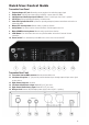
Operation
PEM-1000T Transmitter
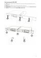
1. Rack-mounting the transmitter
The PEM-1000T requires no installation and can be used on any flat surface. However, in some applications rack
mounting is preferred. There are 2 options available for rack-mounting the PEM-1000T transmitter: singly or
side-by-side with another PEM-1000T transmitter.
• Single mounting: The optional RKT-11 Rack Kit (32) can be attached with the screws provided on the
front of the side panels to enable rackmounting a single PEM-1000T transmitter. Includes front antenna
mount, jack and connecting cable.
• Side-by-side dual mounting: The optional RKT-21 Rack Kit (33) can be attached with the screws
provided on the front of the side panels to enable rackmounting two PEM-1000T transmitters.
(Note: Do not mount the transmitter(s) in a rack directly above an amplifier or other source of high heat–this
could degrade the performance of the PEM-1000T. Always ensure adequate airflow and heat dissipation in any
rack configuration.)
2. Antenna
Connect the Antenna (35) or optional remote antenna on the back panel to the Antenna Jack (11). Optimal
antenna position is vertical. For maximum range, it is always best to maintain a line of sight (no obstructions)
between the transmitter antenna and the receiver(s) at all times whenever possible.
3. Powering the Transmitter
Plug the 12V-15V/1000mA DC Adapter (34) provided into the DC Input Jack (16) on the back of the receiver.
Then plug the power supply into an AC outlet. Press the Power Switch (10) once to turn on the transmitter. The
backlight LCD Display (4) will now light and the transmitter is operational. The LCD display will be lit up and
meantime all the relative information will be displaying on the screen, when the PLL circuit has been locked the
transmitter will start to transmit the signal.
4. Connecting the Audio Input
The PEM-1000T transmitter features a 1/4” TRS unbalanced and balanced XLR for the LEFT Input (14) and
RIGHT Input (15) combo sockets for inputting Line Level. The pass through LEFT and RIGHT output 1/4” TRS
unbalanced for daisy chain audio. The audio signal input can be chosen to be stereo or mono signal. If mono, the
input should be gone through AF IN RIGHT input (15) using XLR balanced input or 1/4” unbalanced plug, the
socket is a combo socket to be able to use the both plugs but only one a time.
(Please note: The signal input level is line level, if need to input Mic level, then it has to be amplified before
inputting, otherwise the sensitivity is not enough, we recommend to first connect with the monitoring output on
the mixer first.)
5. Set the proper audio input level
The strength of the audio input signal will be displaying on the two LED Indicators (3) on the front-left panel.
Adjusting the output level properly makes three LEDs to be lit up. When input level is higher, the four LEDs lit up.
If more than 4 LEDs are lit up the fifth red LED will be lighted to show the input signal has been too strong. So,
adjust the input properly to make sure the S/N ratio and dynamic range are the best to avoid distortion.
(Note: As when making any connection, make sure that the PEM-1000T Volume Knob (2) and the console
output levels are set at minimum volume before plugging into the transmitter. This will avoid possible loud
transients in the PEM-1000R receiver if it is already turned on, and with earphones plugged into the user’s ears.)
9
6. Monitoring on audio signal and connection with earphones
The sound technician can monitor the signal being transmitted with a pair of wired headphones via the stereo
1/4” TRS Earphone Output Jack (1). The volume can be adjusted as desired with the Volume Knob (2). Both
the left and right channels of a stereo signal are adjusted simultaneously by this control in the same manner. To
monitor the sound, plug the stereo earphones into the earphone/headphone output jack, the earphone jack must
be stereo 1/4”at the same time please rotate the volume knob to adjust the proper monitoring volume.
(Please note: In order to protect your ears, the volume must be adjusted properly, it can’t be too loud, and if too
loud the earphone output will be distorted.)
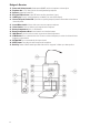
7. Transmitter function set up procedure:
SET Button (7): This button has five functions/menus and works conjunction with the UP (6), or DOWN (8),
they are explained as below:
MAIN DISPLAY➞SET CH➞MODE➞GROUP➞RF PWR➞AF IN➞EXIT
SET Button Illustration:
a. Press the SET Up Button to select SET CH menu, press Manual UP or DOWN button to increase or
decrease the frequency to get the ideal one, meanwhile you can see the frequencies are changed per 125
KHz on the LCD displaying screen.
b. Press the SET Up Button again to select MODE menu, press Manual Up button to be in Stereo mode and
press Manual Down button to be in Mono mode (only R input is used).
c. Press the SET Up Button third time to enter GROUP menu, press Manual Up or Down to increase or
decrease the frequencies to get the wanted frequency, meanwhile you can see the channel numbers are
changed per 10 CH a time on the LCD displaying screen.
d. Press the SET Button the fourth time to select RF PWR menu, press Manual Up or Down to choose the
emission power HI or LOW. It has been preset to be LOW power at 10mW, HI is 100mW. Please kindly
check with your local wireless transmission control gets the relative regulation on its allowable power limit.
e. Press the SET Button the fifth time entering input AF IN menu, press Up or Down to choose the max audio
input level, either +4dB or +10dB.
f. Press the SET Up Button again to EXIT menu, in this preset menu after 8 seconds the unit will be existed to
the default main menu automatically.