
Use Instruction
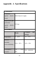
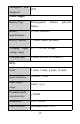
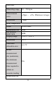
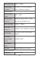
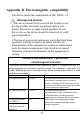
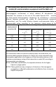
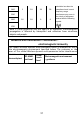
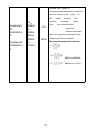
Table Of Contents
- 1.Introduction
- 2.Product introduction
- 3.Preparation before use
- 4.How to use
- 4.1Before use
- 4.2ECG lead wire, temperature probe and blood oxygen
- A.Use of ECG lead wire, body temperature probe and
- B.ECG lead wire placement
- Lead
- Color
- Body surface position (common name)
- 12-lead electrode cable
- RA
- White
- Intersection point between the midline of the righ
- LA
- Black
- The intersection of the left midline of the clavic
- RL
- Green
- Right lower abdomen (right leg)
- LL
- Red
- Left lower abdomen (left leg)
- V1
- Red
- Thoracic lead V1: the fourth intercostal space at
- V2
- Yellow
- Thoracic lead V2: the fourth intercostal space at
- V3
- Green
- Chest lead V3: midway between V2 and V4
- V4
- Blue
- Thoracic lead V4: midclavicular line at the fifth
- V5
- Orange
- Chest lead V5: at the front axillary line, at the
- V6
- Purple
- Chest lead V6: at the mid-axillary line, at the sa
- 6 lead electrode cable
- RA
- White
- Intersection point between the midline of the righ
- LA
- Black
- The intersection of the left midline of the clavic
- RL
- Green
- Right lower abdomen (right leg)
- LL
- Red
- Left lower abdomen (left leg)
- V1
- Red
- Thoracic lead V1: the fourth intercostal space at
- V5
- Orange
- Chest lead V5: at the front axillary line, at the
- 5 lead electrode cable
- RA
- White
- Intersection point between the midline of the righ
- LA
- Black
- The intersection of the left midline of the clavic
- RL
- Green
- Right lower abdomen (right leg)
- LL
- Red
- Left lower abdomen (left leg)
- V1
- Red
- Thoracic lead V1: the fourth intercostal space at
- 3 lead electrode cable
- RA
- White
- Intersection point between the midline of the righ
- LA
- Black
- The intersection of the left midline of the clavic
- LL
- Red
- Left lower abdomen (left leg)
- C.Spo2 probe placement
- D.Temperature probe placement
- 4.3Measurement process
- 4.4Data view
- 4.5 Charging
- 5.Care and maintenance
- 6.Attachment list
- Appendix A Specifications
- Appendix B Electromagnetic compatibility

32
Appendix B Electromagnetic compatibility
The device meets the requirements of IEC 60601-1-2.
Warnings and Cautions
•
This device should not be used in the vicinity or on
the top of other electronic equipment such as cell
phone, transceiver or radio control products. If you
have to do so, the device should be observed to verify
normal operation.
• The use of accessories and power cord other than those
specified, with the exception of cables sold by the
manufacturer of the equipment or system as replacement
parts for internal components, may result in increased
emissions or decreased immunity of the equipment or
system.
Guidance and manufacturer
’
s declaration
– electromagnetic emissions
The model Wireless dynamic multi-parameter holter is intended for use in the
electromagnetic environment specified below. The customer or the user of the
model Wireless dynamic multi-parameter holter should assure that it is used in
such an environment.
Emissions test
Compliance
Electromagnetic environment – guidance
RF emissions CISPR 11
Group 1
The model Wireless dynamic multi-parameter
holter uses RF energy only for its internal
function. Therefore, its RF emissions are very
low and are not likely to cause any interference
in nearby electronic equipment.
RF emissions CISPR 11
Class B
The model Wireless dynamic
multi-parameter holter is suitable for use in
all establishments, including domestic
establishments and those directly connected
to the public low-voltage power supply
network that supplies buildings used for
domestic purposes.
Harmonic emissions
IEC 61000-3-2
n.a.
Voltage fluctuations/
flicker emissions IEC
61000-3-3