
User's Manual
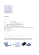


2. Powered by PoE Switch
The connection diagram shows as P2, Internet cable from PoE Switch to Ceiling AP’s WAN Port, then PC access into
ceiling AP wired/wireless.
Pls note, if the PD Wireless AP support 24V passive PoE, then the PoE switch should be 24V Passive PoE,.
If the PD wireless AP support 48V IEEE 802.3af standard PoE, m the PoE switch should comply with 802.3af 48V PoE
standard.
P2
Op e r ation M o d e :
The r e a r e t h r e e o p e r a t i o n m o d e o n t h i s wire l e s s AP :
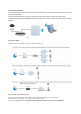
P 3 O p era t i o n M o d e
Conn e c t Wireless AP w it h P C :
Use c a n c o n n e c t t h e P C wi t h w i r e l e s s AP b y W i r e l e s s S S I D a n d L A N c a b l e :
The d i a g r a m o f wir e l e s s c o n n ec t i o n s h o wed a s f o l l o w:
Pls n ot e : t he d e f a u l t S S I D i s W i r el ess AP2.4G/ 5.8G, SS I D ’s pa s s w o r d i s 66 6 6 6 6 6 6