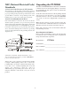
NOTE This manual is provided for REFERENCE purposes only. Information contained in this manual, including contact and warranty information, may NOT be current or correct.
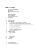
Table of Contents 3 4 5 5 6 6 7 7 7 8 9-10 11-13 13-15 16-18 18 19 20 21 22 23 24 25 26 27 28 29 30 30 30 30 30 30-31 31 31-32 32 33 33 34 34-36 37 38 Thank You for your PT-7020A Purchase Safety Precautions NEC (National Electrical Code) Standards Unpacking the PT-7020A Features Connectivity Installation and Connections AC Power Considerations Connection Tips for Superior Sound Connection Types Front Panel Features Rear Panel Layout Remote Control Operating the PT-7020A Connection Diagrams Connecting a DVD
Thank You Thank you for purchasing the Sherbourn PT-7020A preamp processor. We know you have a choice of many fine products and your selection of Sherbourn product is truly appreciated. As with all of the Sherbourn family of products, the PT-7020A is designed, engineered and produced with the finest quality components to ensure that you enjoy the latest technologies available and can count on many years of reliable and exquisite audio and video performance.
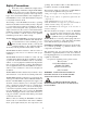
Safety Precautions openings. Care should be taken so that small objects do not fall into the inside of the PT-7020A. Read this Owner’s Manual thoroughly before attempting to install and configure the PT-7020A. All the safety and operation instructions should be read before any operation of the component(s) begin. After successful installation and configuration of the PT-7020A, be sure to retain this manual in a safe place for any future reference needs.
NEC (National Electrical Code) Unpacking the PT-7020A The Sherbourn PT-7020A Pre/Pro should reach you in flawless Standards condition. If you notice any shipping damage or other issues A Note for the Cable Television (CATV) Installer upon unpacking the unit, please contact your Sherbourn Retailer immediately.
Features Connectivity Twin Cirrus® 32 bit dual core DSP’s (5) HDMI inputs and (1) HDMI output.
Installation and Connections Connection Tips for Superior Sound Observe the following precautions when choosing a location for your Sherbourn PT-7020A 1. Protect it from prolonged exposure to direct sunlight and other direct sources of heat, such as heating vents and radiators. Before setting up your new system, please consider the following: Whenever possible, route the power cord away from the signal cables or speaker wires to prevent any hum or interference heard in the speakers. 2.
Connection Types Plus, PLIIx and DTS-HD Master Audio, DTS-HD High Resolution Audio, DTS Digital Surround ES - Neo:6 - 92/ 24). The Sherbourn PT-7020A has four types of video connections on board (3 Analog and 1 Digital) and 4 types of audio connections on board HDMI, RCA, OPTICAL and BALANCED (Subwoofer Only). Only HDMI video inputs and outputs are supported onboard the Sherbourn PT-7020A chassis. This offers full compatibility with 5 HDMI input devices and one HDMI output to an HDMI display device.
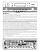
Front Panel Features becomes less negative as the volume increases. The PT7020A volume control is velocity sensitive. If turned slowly, the volume will change in small increments. If rotated quickly, level change will be made in larger increments. 1. Power Button and Standby LED The Power button is a non-latching momentary button that turns the PT-7020A on or off.
more, the tuner will automatically keep tuning stations. Press UP or DOWN once again to stop when it reaches a station you like. Preset Tuner Memory Buttons - Press just the numbers (do not press DIRECT) for tuning the memorized presets. 9. DIM Button The front panel lights have ten levels of illumination - 10 being the brightest, 1 being the dimmest and off to eliminate all illumination. 10. Navigation Buttons 5.
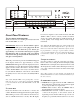
Rear Panel Layout 1. FM Antenna The supplied FM antenna fits this “F-Type” screw on connector. Other antennas can be fitted for improved reception. 2. AM Antenna These connections are for the included AM loop antenna. 3. 7.1 Channel Analog Input These analog audio inputs can connect to the outputs of an external multi-channel processor, or a source component such as DVD-Audio, SACD or a DVD player with its own surround decoder. You can assign this as an input from the front panel or remote control.
10. Trigger out These trigger connectors provide an electrical signal. These triggers can be used to switch on and off compatible pieces of equipment (amplifiers, DVD player, CD player etc). There are four trigger outputs on the PT-7020A, each capable of outputting a 12V signal. The triggers are designed to accept a mono 3.5mm jack; tip is the trigger positive output, sleeve is the ground. puts. Note that component video provides the best picture compared to composite or S-Video.
Remote Control back, right surround and one subwoofer (LFE) output. If your amplifier has a choice of inputs, we recommend using the XLR balanced type. This gives better noise rejection, especially for longer cable runs. 19. IEC Line Cord Socket The PT-7020A comes with a detachable IEC line cord which connects here. Plug the line cord into an AC wall socket or power strip which is correctly configured with the voltage and current supply specified for the PT7020A.
Controls 1. ON This button powers the PT-7020A on from standby mode. When the ON button is pressed, the blue light next to the power button will turn off, and LOADING will appear in the display window for approximately 3 seconds, and Sherbourn will appear next in the display window for approximately 3 seconds. The last selected input will appear and the volume will return to the last selected volume. The PT7020A is now ready to use. This can also be done with the POWER button on the front of the unit. 2.
12. SCAN/PRESET This scans the preset stations that you set up in the TUNER setup menu. This allows you to navigate manually through your preset stations. 13. DOWN/UP These buttons allow you to scan up or down through the tuner presets. 14. ZONE 2 This section of the remote allows you to control the Zone-2 section of the PT-7020A. These settings would have been setup in the Zone-2 section of the SETUP menu. POWER This powers on and off your Zone 2.
Operating the PT-7020A This will take you to the currently selected input MODE display screen. As you can see the MODE option that was set up is highlighted. Under the DSP mode over to the right are the different Processing options available to you. Note: These will change with each MODE you have selected. USING THE OSD (On Screen Display) Sherbourn’s PT-7020A has an easy to use intuitive OSD with an adjustable transparency presented over live video (HDMI only).
Input Setup This is where you set up the individual inputs to your specifications. Each input has seven choices; VISIBLE, AUDIO, VIDEO, INPUT LEVEL, LIPSYNC, TRIGGER AND EQ MODE. Each input can be setup in multiple configurations for a single source unit. INPUT 2, INPUT 3 and INPUT 4 can be all used for the same source unit. In this case we will use a Blu-Ray player. For INPUT 2 you can set the VIDEO to HDMI and the AUDIO to HDMI for Blu-Ray movies.
Direct, DSP, PLIIx and NEO:6. If you set this to Direct, every time you are on this input and the PT-7020A recognizes an analog source the PT-7020A will automatically be set to direct. Each audio mode can have different presets. Direct mode bypasses all DSP, Tone and Bass management circuits. It is stereo only and offers the shortest signal path through the PT-7020A. Only the front left and right speakers are engaged.
Connection Diagram 1: Connecting a DVD-Video and/or Blu-Ray Player (Using HDMI) This configuration shows a DVD-Video and/or Blu-Ray player connection where the audio and video output from the DVD-Video and/or Blu-Ray player is taken through the HDMI connection. When you select DVD on the PT-7020A, the audio output from the DVD player will play through the PT-7020A and video will appear on the TV or projector (remember that you must first select the correct input on the TV).
Connection Diagram 2 Connecting a DVD-Video Player (Using Digital Audio + Component Video) This configuration shows a DVD-Video player connection where the audio output from the DVDVideo player is taken from the digital output (Coaxial or Optical) and video output is taken from the Component Video outputs (the Red/Blue/Green trio).
Connection Diagram 3 Connecting a DVD-Video Player (Using Analog Audio + Composite Video) This configuration shows a DVD-Video player connection where the audio output from the DVD-Video player is taken from the analog outputs (Red and White RCA jacks) and video output is taken from the Composite Video output (the Yellow RCA jack).
Connection Diagram 4 Connecting to the Cable or Satellite Box and TV (Using Digital Audio + Component Video) This configuration shows the PT-7020A connections to the “main” video display where video output is taken from the Component Video outputs (the Red/Blue/Green trio) labeled “Component” on the back panel of the PT-7020A. Audio in this case is connected between the set top box and the PT-7020A using a Digital Audio (Coaxial or Optical) connection.
Connection Diagram 5 Connecting the 7.1 Channel Analog Inputs This configuration shows the 7.1 channel inputs that would be used for a DVD-1, SACD and other DSP bypass situations. You may also elect to use this input choice if your DVD-Video player has its own surround processor, or if you have an external (dedicated) surround processor, in which case, the Digital Audio connection would also be present. The 7.
Connection Diagram 6 Connecting a CD Player (Digital Audio) This configuration shows a CD Player connection where the audio output from the CD Player is taken from the digital audio output (Orange RCA jack in the “Digital Inputs” section). When you select CD on PT-7020A, the audio output from the CD player will play through the audio system.
Connection Diagram 7 Connecting a Cassette Tape or DAT Deck This configuration shows a Cassette Tape Deck connection where the audio output is taken from the left and right audio outputs (may also be labeled PLAY). If you plan to use the Cassette Tape Deck for recording, you also must connect the PT-7020A’s TAPE audio outputs into the Cassette Tape Deck inputs (may also be labeled RECORD). Depending on the type of tape deck you connect, the inputs and output on the PT7020A can be connected to TAPE or DAT.
Connection Diagram 8 Connecting the AM and FM Antennas This configuration shows the AM and FM antenna connections. The AM antenna should be a “loop” style antenna with two wires that connect into the AM ANTENNA receptacles. The FM antenna must terminate into an “F Style” connector and has a 75 Ohm impedance. Position the AM and FM antennas where reception is best. The AM loop antenna that has been included with the PT-7020A has been matched to the AM tuner for optimum reception.
Connection Diagram 9 Connecting an Amplifier (7.1 Configuration) This configuration shows the MAIN ZONE connections to a multi-channel amplifier configured for 7 channel operation. Also note the connection of the 12 VDC trigger to turn on the amplifier. In this configuration the PT-7020A is connected to 7 channels of amplification via XLR outputs. The XLR SUBWOOFER output would connect to the input of a powered subwoofer.
Connection Diagram 10 Connecting a Powered Subwoofer via XLR or RCA This configuration shows the MAIN ZONE connections to a multi-channel amplifier as in the previous connection illustration, only the powered subwoofer connection utilized the XLR output from PT-7020A. The advantage of the XLR balanced connections is that they have a much higher rejection to any radiated noise from AC line cord interference. Note: As an alternative to the XLR SUB Output, there is (1) RCA SUB output in the 7.
Connection Diagram 11 Connecting an Amplifier (Zone 2) This configuration shows the ZONE 2 connections to two channels of a multi-channel amplifier. In this configuration you would run just the two channels for Zone 2. If you are connecting Zone 2 in this way, you should connect both the MAIN Zone and Zone 2 trigger inputs to turn on the amplifier.
Speaker Placement Tips than this, you can experiment by adding sound deadening material such as drapes on the walls to reduce any unwanted reflections. Tips Before Beginning Read this section thoroughly. There are a number of ways in which it may seem aesthetically pleasing to place speakers in a room that will ultimately result in a sound quality compromise. The placement of speakers is equally as important as the room itself.
The PT-7020A can be configured for one or two surround back speakers. Ideally, all the surround speakers should be of the same make and model, and fitted at similar heights to produce a smooth continuous sound field. If you are connecting one surround back speaker, connect its amplifier input to the PT-7020A LEFT CHANNEL SURROUND BACK output. Place the speaker behind your listening position. Subwoofer Location The PT-7020A has two subwoofer outputs, the unbalanced RCA output and the balanced sub output.
Speaker Setup increments. (Use this selection for manual set up only. Sherbourn room EQ will set the distances for you). First measure and write down all the speaker distances from where you normally sit. This is where you set up your SPEAKER SIZE, CROSSOVER, LEVEL CALIBRATION, SPEAKER DISTANCE, SPEAKER LEVEL, LFE LEVEL and HDMI AUDIO OUTPUT. From the SPEAKER SETUP menu scroll to SPEAKER DISTANCE and press ENTER. You will see the list of speakers on the left and distance on the right.
Sherbourn Room Correction (SRC) The SRC Auto Room Correction is able to correct deficiencies in your room acoustics by flattening the response. This does not necessarily mean that this correct, only your ears can tell you what sounds good to you. The SRC gives you a base starting point. Configuring SRC (Sherbourn Room Calibration) Hook the supplied microphone to the back of the PT7020A. Go to the setup menu and scroll down to the SRC / EQ and hit enter. The SRC / EQ screen opens.
2nd Zone Operation Troubleshooting Guide With the Zone-2 feature active you can listen to what is playing in the main theater or any other analog input somewhere else in the house. If you want to listen to the main theater in Zone-2 the PT-7020A will down mix the audio to two-channel. You can also listen to another analog source (ex. CD Player) while a Blu-Ray (DVD) is playing in the main theater as long as the source is connected to one of the analog inputs listed below.
menu, otherwise it may just play stereo into your PT7020A and you won’t get the true LFE signal to the subwoofer. Poor AM Reception Often one of the main complaints about poor AM reception is that the same AM station can be heard at different frequencies. Check to see is BOTH wires of the AM loop antenna are connected. A loop antenna is required for AM reception, as it forms part of the frontend tuned circuit. Poor FM Reception The antenna may be incorrectly attached.
Zone 2 does not play digital inputs Zone 2 can play analog sources independent of what is playing in the Main Zone. It cannot play from a digitalonly source unless that input is selected and playing in the Main Zone. To play a source such as a DVD player in Zone 2 independent of the Main Zone, make sure you connect the player’s L/R analog audio output to the PT7020A too.
Five Year Limited Warranty Subject to the terms and conditions stated below, Sherbourn Technologies, Inc. (Sherbourn) warrants to the original owner that this model PT-7020A shall be free from defects in workmanship or materials for a term of five (5) years from its date of purchase from an Authorized Sherbourn Dealer. Transfer of this product by its original owner (the ‘Owner’) will automatically terminate this Warranty regardless of when occurring.
Licensing and Trademark Disclosures Dolby Volume Benefits Consistent volume across all content, programs, and input sources Reference-quality listening experience at any volume level Eliminates need to constantly adjust volume Can be adjusted to personal preference and listening conditions Full, rich, and consistent experience at all volume levels Improved surround perception at low volume levels No artifacts or audible side effects DTS-HD Master Audio This product is manufactured under lice