
Owner`s manual


Page 6
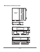
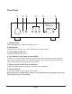
Rear Panel
1, 2. Inputs (one stereo pair for each input; unbalanced)
Connect your line level inputs to these.
3. Outputs (one stereo pair; unbalanced)
Stereo passthrough output carries the selected input signal for chaining other devices.
4. Speaker Outputs (two each for left and right channel)
Phoenix-type connectors for connecting up to two pairs of speakers.
5. Power Switch
Switches the AC mains power to the PA 2-50 On and Off. When this switch is Off, the PA 2-50 will
not respond to trigger signals or manual controls.
6. Input Voltage Selector Switch
Always ensure that this switch is set for the proper line voltage for your area and installation.
7. RS-232 Serial Remote Control Interface
Accepts RS-232 control codes from a wired serial remote control.
Refer to the Remote Control Codes and Signal Specications section for details.
8. Trigger Input
The Trigger Input is used to allow other trigger-enabled equipment to switch the PA 2-50 between
On and Standby.
LEFT RIGHT LEFT RIGHT
RS-232 CONTROL
INPUT 1 INPUT 2 OUTPUT
SPEAKER OUTPUTS
+ - + - + - + -
TRIGGER
IN
IR IN
ON
OFF
AUTO
AC INPUT
ON OFF
POWER
115
L
R
1 5432 6
7 119 108