SHERLINE 8-Direction Mill P/N 2000/2010* *NOTE: These instructions also apply in general to the Model 5650/5660 upgrade from standard Sherline mill to 8-direction, the Model 3580/3585 multi-direction vertical milling column and the Model 5680/5685 upgrade from standard vertical milling column to multi-direction vertical milling column. The drawings and exploded view shown here cover the general aspects of assembling and aligning a multi-direction mill.
Using the multidirectional milling capabilities The design of the 8-direction mill allows you to do everything that could be done with previous models of the Sherline mill plus much more. Now angled holes can be drilled or milling operations can be completed from almost any angle on parts mounted square to the table. The increased swing and movement of the column allows larger surfaces to be machined, eliminating the need for the horizontal milling conversion.
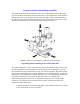
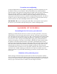
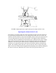
2. Screw the arm hold-down bolt (P/N 5613) into the top of the round column base and tighten with an adjustable wrench. Two flat indentations are provided for the wrench to grip. 3. Slip the round column top (P/N 5655) over the pin and rotate it until the flat sides are parallel to the mill base with the engraved indicator line on the same side as the X-axis handwheel. 4. Using an 11/16" or 17mm* wrench, loosen the flange nut holding the bed and swing arm together.
The mill is now ready to be positioned for use if you will be doing angled operations or ready to be squared up if you will be milling square parts. The following instructions will explain the steps used to "indicate in" the head of the mill so it will be square to the table. Lubrication, and when NOT to lubricate certain surfaces The mating surfaces of the arm, the column and the column cap are to be kept free from lubrication.
Precautions on overtightening As with all adjustments on any machine, overtightening can distort components or ruin the built-in accuracy of your machine. This is particularly true on smaller machines where the power of the operator is much greater in relation to the size of the components than it is on larger machines. It is possible to deform the T-slot, which results in a worktable that isn't flat.
Why aren't there alignment pins to square up the machine? If you are a novice to machining, you probably believe a machine should be designed so that a couple of pins could be dropped into holes, squaring up the machine and eliminating this whole process. After all, that is the way they do it with woodworking machinery. The truth is the tolerances that work well for wood cutting tools simply aren't accurate enough for most metalworking tools. You just can't hold the tolerances required with "pins".
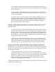
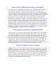
FIGURE 2-Checking for built in error in the table travel along the Y-axis Squaring up the ram (See Figure 3.) The next decision to make is where the spindle is to be located. With all the adjustments that can be made with the 8-direction mill you'll probably start with the spindle located near the middle of the X/Y table movements. Something that isn't too obvious should be considered now.
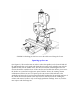
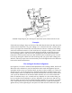
FIGURE 3-Squaring up the ram parallel to the Y-axis. The indicator can be held with a chuck on the table or a mill vise as shown here. Squaring the column with the X-axis (See Figure 4.) The column should next be squared with the X-axis. This is accomplished with an indicator mounted in the spindle.
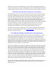
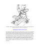
FIGURE 4-Squaring the left to right rotation of the column with the X-axis Squaring the column with the Y-axis (See Figure 5.) Loosen the flange nut on the horizontal pivot pin so that the column can be moved using the adjustment screw in the alignment block but there is no slop in the assembly. The tilt is harder to set because the spindle doesn't rotate at the pivot point, but once you understand this, the task becomes simpler.
FIGURE 5-Squaring the fore and aft pivot movement of the column with the Y-axis Example: If the indicator reading is larger at the front of the table than the back, then that means the column must be tilted back. Say your reading is "0" at the back and .010" (.25mm) at the front. If you tipped the column back until the indicator read zero at the front, the reading at the back would not remain at "0" but would now be a negative reading.
you ever want to check alignment of the key to the column bed, mount a dial indicator in the spindle. Raise and lower the head while reading the vertical edge of a precision square. Adjust the rotating column until there is no error as the indicator moves up and down the square. Now read the table with the indicator. If the slot and key are perfect there shouldn't be any error, but in most cases there will be a small amount.
will decrease. Being able to accurately indicate in a mill is one of the skills that must be developed by any machinist who plans on making accurate parts. Though the adjustments on larger machines may be made in slightly different ways, the skills and procedures you learn here can be applied to other machines as well. Using the column spacer block In normal use the column spacer block will not be required.
FIGURE 7—This photo above shows the column blocks repositioned to lower the ram. The column top is placed upside down above the swing arm rather than below it. Should you wish to work on extremely tall setups that combine several holding devices (i.e.
want to create a customer who spends all his time trying to achieve perfect alignment for work that doesn't require it and ends up never using the machine. Engineering is always a compromise. I deal with this fact with each new product that I design. While our machines aren't accurate enough for some customers, they are still too expensive for others. I hope you are pleased with the new capabilities this multi-direction mill can bring to your shop.
EXPLODED VIEW (Drawing updated 3/11/99)
REPLACEMENT PARTS LIST REF. NO. 1 2 3 4 5 PART NO. 3516 3517 4034 4033 5624 5601 NO. REQ.
40176 1 Saddle locking lever (Inch) 1 1 Saddle locking lever (Metric) Saddle travel extension Z-axis leadscrew (Inch) 28 29 41176 40175 45011 30 45161 Z-axis leadscrew (Metric)