
Using a model mill instructions

will decrease. Being able to accurately indicate in a mill is one of the skills that must be
developed by any machinist who plans on making accurate parts. Though the adjustments
on larger machines may be made in slightly different ways, the skills and procedures you
learn here can be applied to other machines as well.
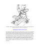
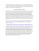
Using the column spacer block
In normal use the column spacer block will not be required. However, if you are working
on a larger part or your setup requires more clearance under the swing arm, the spacer
block can be installed to raise the column an additional two inches. (Installation will be
made easier if you first remove the headstock/motor unit to reduce the weight of the
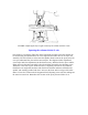
column.) To install the spacer block, remove the flange nut on top of the column hold-
down bolt, and lift off the hold-down washer so that the entire column top and swing arm
assembly can be lifted off of the hold-down bolt. Screw the extension bolt onto the end of
the column bolt and tighten with an adjustable wrench. Slide the column spacer over the
bolt and reinstall the column top and swing arm assembly. Reinstall the headstock/motor
unit.
NOTE: The column spacer block is included as standard with the Model 2000 mill. It is
optional at extra cost on all mill column upgrades and 8-direction vertical milling
columns and upgrades.
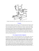
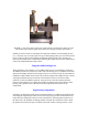
Working with setups that require extremely low or high column travel
An upgrade to the Model 2000 mill was introduced in March, 1999. It adds 1.6" of travel
to the lower end of the Z-axis movement so that end mills can be brought down below the
surface of the table for working on the edge of parts. This travel extension is now
standard on all Model 2000 mills. The headstock may be lowered even more by placing
the column top (P/N 5655) above the swing arm instead of below it. Remove the flange
nut, hold-down washer and swing arm. Place the swing arm over the hold-down bolt
directly on top of the column base (P/N 5666). Place the column top back onto the hold-
down bolt upside down and replace the hold-down washer and flange nut. (See Figure 7
below.) Although you cannot use the alignment lines to help square up the head, this
makes for a very strong and stable setup. In most cases, however, the new travel
extension will make this procedure unnecessary.