
Using a model mill instructions
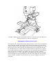
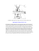
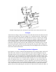
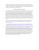
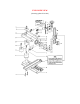

FIGURE 7—This photo above shows the column blocks repositioned to lower the ram.
The column top is placed upside down above the swing arm rather than below it.
Should you wish to work on extremely tall setups that combine several holding devices
(i.e., a chuck on top of a rotary table on top of a tilting angle table) you can extend Z-axis
travel on the top end by either adding an additional spacer block to the column or by
removing the saddle travel extension and attaching the saddle directly to the saddle nut as
is done on standard Sherline mills or both.
Using the saddle locking lever
Along with the travel extension, a new saddle locking lever was installed to replace the
old saddle friction lock used prior to 2/99. This new locking lever is standard on all mills
and vertical milling columns as of that date. This lever is located on the Z-axis leadscrew
behind the saddle. When turned to the full clockwise position the saddle will move freely.
A spring-loaded ball locates in a detent in the bottom of the lever to hold it in this
position. To lock the saddle in position, move the lever to the full counterclockwise
position. This locks the lever against the saddle nut which prevents the leadscrew from
turning. The exploded view at the bottom of this page shows the location of the
components.
Engineering compromises
I'm always at odds with myself when I write instructions on complicated procedures like
describing the alignment procedure for this mill. By giving you this much information I
know that I am making life easier for some customers by answering their questions. At
the same time I am probably confusing another customer who would never have asked
the question because of the type of work that the mill or lathe is being used for. I don't