
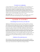
Using a model mill instructions
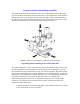
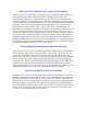
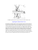
2. Screw the arm hold-down bolt (P/N 5613) into the top of the round column
base and tighten with an adjustable wrench. Two flat indentations are provided for
the wrench to grip.
3. Slip the round column top (P/N 5655) over the pin and rotate it until the flat
sides are parallel to the mill base with the engraved indicator line on the same side
as the X-axis handwheel.
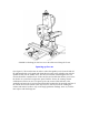
4. Using an 11/16" or 17mm* wrench, loosen the flange nut holding the bed and
swing arm together. Rotate the bed away from the swing arm until they are at
approximately a 90° angle to each other. Retighten the flange nut firmly to hold
the column in this position. Discard the protective spacer that was installed
between the bed and arm during shipping.
*NOTE: A 17mm wrench usually works on an 11/16" hex nut but is a close fit. If your
17mm wrench is too tight and you don't have any inch tools you will have to use an
adjustable wrench.
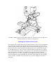
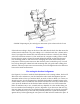
5. Set the swing arm over the column and align it approximately square with the
mill base and in about the center of its travel. Make sure the swing arm registers
on the flats of the column top and is properly seated. While still holding the swing
arm unit in place, set the hold-down washer (P/N 5620) over the end of the bolt.
Put a flange nut on the end of the bolt and tighten it against the hold-down washer
firmly to lock the swing arm in place.
6. Place the column adjustment block (P/N 5635) on top of the swing arm and
attach it with two 10-32 x 5/8" socket head cap screws at both ends. Adjust the 1"
long center bolt so that it is just touching the flat in the bottom of the relieved
section in the top of the pivot knuckle when the column is in the 90° position.
NOTE: If you remove the column adjustment block to accommodate a backward tilt
movement of the column, make sure you replace it when returning the column to an
upright position. It not only serves as a reference point when returning the column to the
90° position, it also keeps it from accidentally swinging down and damaging the table if
the flange nut is loosened.
7. Slip the alignment key* into its keyway in the mill saddle. Place the
headstock/motor/speed control unit over the pin on the mill saddle and over the
alignment key. Tighten the set screw in the side of the headstock to hold the entire
unit in place. Recheck to be sure you have tightened the flange nut on the
shouldered bolt pivot pin securely so that all the weight of the column is not
resting on the column adjustment block bolt.
*NOTE: The alignment key is precision ground and will only fit into the keyway with the
ground edges toward the sides.