
Using a model mill instructions
Why aren't there alignment pins to square up the machine?
If you are a novice to machining, you probably believe a machine should be designed so
that a couple of pins could be dropped into holes, squaring up the machine and
eliminating this whole process. After all, that is the way they do it with woodworking
machinery. The truth is the tolerances that work well for wood cutting tools simply aren't
accurate enough for most metalworking tools. You just can't hold the tolerances required
with "pins". When they fit tight enough to lock the head square to the table you can't
remove them to do work that isn't square. They become more of a problem than the
problem they were installed to eliminate. For example, an alignment or assembly error of
.010" in a wooden kitchen table will never be noticed. Usually the floor it sits on is not
even flat. It would be a waste of time and effort to make it more accurate than it has to be.
On the other hand, a cylinder that has been bored out of square with the crankshaft in an
automobile engine could wear the entire engine at an alarming rate. The piston goes up
and down a million times in a normal day's use. The additional cost in fuel and shortened
life demands accuracy. The Model 2000 Sherline mill allows you to provide this accuracy
by making the adjustments required to suit a particular job.
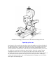
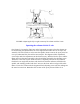
Start by getting the column close to square with the table
The first place to start is to get the column approximately square with the table using the
pointers and laser engraved scales on the machine. The first time you set it up you will
have to use a machinist's square on the side-to-side column rotary adjustment as the
pointer will not have been "zeroed in" yet. None of these adjustments must be extremely
precise at this point because a finger type dial indicator will be used to make the final
adjustments later. Remove the headstock/motor/speed control unit from the saddle. Place
a machinist's square on the table and line up the front of the saddle to get the column
approximately square front to back. Then line up on the right side of the saddle to get the
column approximately square side to side. Reinstall the headstock assembly.
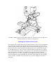
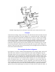
Check for any built-in error in your machine
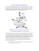
(See Figure 2.) To check the built-in error of the machine use a dial indicator mounted in
the spindle. Move the table under spindle with the Y-axis handwheel and note the error.
This error will usually be around .001" to .002" (.05mm) in 3" (76mm). (Remember the
components are not precision ground, they are precision milled.) When squaring the head
this error should be accounted for. Remember you are squaring the head and spindle to
base of the machine where the saddle travels, not the surface of the table itself. The head
doesn't have to be square for this operation as long as you don't rotate the spindle since
you are only checking for square in one direction.