
Using a model mill instructions
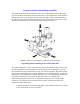
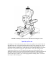
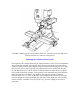
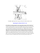
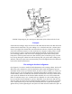

FIGURE 3-Squaring up the ram parallel to the Y-axis. The indicator can be held with a
chuck on the table or a mill vise as shown here.
Squaring the column with the X-axis
(See Figure 4.) The column should next be squared with the X-axis. This is accomplished
with an indicator mounted in the spindle. Have the four socket head cap screws used to
clamp the column rotation tight enough to keep the column from rotating, but not so tight
that you can't move it with a light tap from a plastic mallet to the column bed. Because
the axis that allows you to tilt the column in and out hasn't been squared yet you should
only read the indicator at the same Y-axis location on the worktable that you used before.
Offset the indicator at an angle in the spindle so that when the spindle is rotated it
describes about a 2" to 3" circle on the table. Take readings at the extreme left and right
positions. Adjust the column with light taps until there is little difference in the readings
at either extreme. I wouldn't try to get it perfect yet, just close enough so there isn't a
gross error.