
Using a model mill instructions
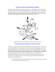
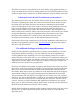
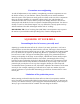
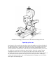
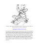
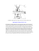
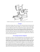

FIGURE 4-Squaring the left to right rotation of the column with the X-axis
Squaring the column with the Y-axis
(See Figure 5.) Loosen the flange nut on the horizontal pivot pin so that the column can
be moved using the adjustment screw in the alignment block but there is no slop in the
assembly. The tilt is harder to set because the spindle doesn't rotate at the pivot point, but
once you understand this, the task becomes simpler. The alignment block adjustment
screw helps make fine adjustments in this direction easy. With the block in place and the
flange nut loose the entire assembly is kept from falling forward by the adjusting screw.
This block can be left in place unless the ram is completely retracted or the column is
tilted back at an angle that interferes with the block. With the indicator still held in the
spindle, take readings parallel with the Y-axis near the front and rear edges of the table.
Raise or lower the column with the alignment block adjusting screw until the readings are
the same front and rear. Remember the location of the pivot point and allow for it.