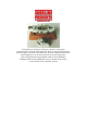
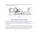
Scotty Hewitt of Van Nuys, California, built this 5" long steam powered tug boat. The tiny steam engine has been test run on compressed air and works great. The boiler is functional too. If Scotty could find a heat source small enough to fire it, the boat could run on its own steam power. This model finished 3rd in the 1996 N.A.M.E.S. show Machinist's Challenge sponsored by SHERLINE. For more details on the contest, see the section on the N.A.M.E.S. Contest.
SHERLINE Lathe and Mill Setup Instructions Getting answers to your questions about machining Over the years we have found that the majority of our customers are both highly intelligent and skilled craftsmen. Often they are also new to machining. The instructions we have included in this book, while far more extensive than anything included with other machine tools, even ones costing thousands of dollars, still only scratch the surface when it comes to machining.
There are no shortcuts Machining is a slow process if parts are made one at a time. The interesting thing is, a skilled machinist may take almost as long to make the same part as a novice. Shortcuts usually end in failure. Unlike some other trades, mistakes cannot be covered up. There are no erasers, white-out or "putting-on tools" for machinists; you simply start over.
2. GROUND ALL TOOLS-If tool is equipped a with three-prong plug, it should be plugged into a three-hole receptacle. If an adapter is used to accommodate a twoprong receptacle, the adapter wire must be attached to a KNOWN GROUND. Never remove third the prong. (See Figure 1.) 3. KEEP GUARDS IN PLACE-and in working order. 4. REMOVE ADJUSTING KEYS AND WRENCHES-Form a habit of checking to see that keys and adjusting wrenches are removed from tool before turning on machine. 5.
21. DON'T LET LONG, THIN STOCK PROTRUDE FROM THE BACK OF THE SPINDLE—Long, thin stock that is unsupported and turned at high RPM can suddenly bend and whip around. 22. WEAR YOUR SAFETY GLASSES-Foresight is better than NO SIGHT! The operation of any power tool can result in foreign objects being thrown into the eyes, which can result in severe eye damage. Always wear safety glasses or eye shields before commencing power tool operation.
lists input voltage as 120VAC, DO NOT ATTEMPT TO CONVERT TO OTHER CURRENTS. Models that can be used with any current have a paper label on the end of the speed control frame which lists the model number as KBLC-240DS. The machines are normally supplied with a USA type plug but can be easily rewired to accept a European or U.K. type plug by attaching the wires using the color codes provided below.
Avoid overtightening! One of the problems with designing and manufacturing metal cutting equipment of this size is that the operator can physically be stronger than the machine, which is not normally the case with larger tools. For example, a 10-pound force applied a couple of inches out on a hex key becomes a 650-pound force at the tip of the screw.
Many fine books have been written on machining techniques and are available at your local library or book store. Although these books will be referring to machines many times larger than Sherline's tools, the principle remains the same. For the best reference that is specific to Sherline tools, see Joe Martin's book, Tabletop Machining. Lubrication MACHINE SLIDES-Use a light oil such as sewing machine oil on all points where there is sliding contact.
FIGURE 2 Next, see that the gib is in the proper position on the saddle. (See Figure 2.) It is taped into position for shipping. Remove the tape holding it in place. If the gib has come off, position it on the gib lock as shown. Set the dovetail of the crosslide over the gib and matching dovetail on the saddle. Slide it onto the saddle about 1/4" (6-7mm) until it stops. (See Figure 3.
engage the threads. Continue to crank the handwheel clockwise until the crosslide is in the desired position on the saddle. FIGURE 4 Mill-column mounting procedure The mill is shipped attached to a piece of plywood to keep it from moving in the box. Before you begin, remove the screws holding the mill base to the plywood. It was installed strictly for packing purposes and will need to be removed so that the column can be installed.
FIGURE 5 Set the column on the base aligned with the mounting holes and hold it in position while you insert the first screw up from the bottom of the base. Hand turn the first screw part way in and then start the second screw. This can be done with the machine upright by letting the base hang over the edge of your table or bench just far enough to expose the first hole. Using the hex key, snug up both screws lightly first, and then tighten evenly.
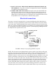
periodically when using the machine, as vibration from operation may cause some fasteners to loosen up. Mounting the motor and speed control unit to the headstock (Refer to the exploded views and number list for part number references.) FIGURE 6-DC Motor and Speed Control Assembly 1. Remove motor pulley from motor shaft. Mount the inner belt guard to the motor using the two standoffs (P/N 4310). Next install the motor pulley (P/N 4336) to the motor shaft and tighten the set screw.
belt is routed properly. Then secure the cover with (2) 1-3/8" pan head screws which go into nuts pressed into the back of the inner belt guard. 5. Attach motor mounting bracket to rear of headstock with two 10-32 x 3/8" socket head screws. There is enough "play" in the mounting holes to allow you to ensure the motor is visually mounted parallel with the spindle axis. (Note: If chip guard is to be mounted, its attachment screw replaces one of these mounting screws.
The advantages of Sherline's DC motor and electronic speed control Sherline's 90 volt DC motor is very smooth and powerful, particularly at low RPM. The specially designed electronics package also provides some unique advantages in addition to smooth speed control with a usable speed range of 70 to 2800 RPM. A special circuit compensates for load, helping to keep RPM constant.
Remember that the circuit breaker turns the speed control off which turns off the motor. If power were to be applied to the speed control with the motor disconnected, it could damage the speed control. Thermal protection is built into your motor to make sure it is not damaged by overloading. Use good common sense when operating the motor, and it will provide many years of trouble free operation.
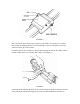
FIGURE 7-Cross section of headstock showing locking screw. The screw in the front center of the headstock has a cone point. The pivot pin has a tapered slot with a corresponding angle. When the screw is tightened, its angled face engages the groove and, because the pivot pin can not come up, it draws the headstock down into position, clamping it into place. If the pin were rigid, it could keep the headstock from pulling down squarely. FIGURE 8-Headstock and alignment key in position over lathe.
The headstock is aligned with the lathe bed or column saddle with a precision ground key that fits into keyways in both parts. It is not square in cross section so it will fit in only one direction. Push the headstock firmly against it as you tighten the hold down screw. The mill headstock has two keyways milled into it so it can be mounted in conventional fashion or at a 90° angle for horizontal milling.
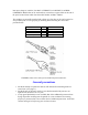
eliminates one of the best features of Sherline machines...the ability to easily be put away for storage. FIGURE 10-Plans for mounting board hole patterns. Confirm actual dimensions from your lathe or mill before drilling. The newly added model 2000 multi-direction mill can be mounted to a board 12" x 18" in a similar fashion. The mill may be mounted in a similar manner on a 10" x 12" to 12" x 24" pre-finished shelf board with rubber feet using 10-32 x 1" screws to attach the mill to the board.
ADJUSTMENTS Two-speed pulley The normal pulley position, which is placing the belt on the larger motor pulley and smaller headstock pulley, will suffice for most of your machining work. Moving the belt to the other position (smaller motor pulley, larger headstock pulley) will provide additional torque at lower RPM. It is particularly useful when turning larger diameter parts with the optional riser block in place. FIGURE 11-The two pulley positions.
of high speed operation may bring about excessive temperature. If this is your case, the preload may be reduced slightly. To change the adjustment, remove the spindle pulley, loosen the set screw in the preload nut and back the preload nut off four degrees of rotation (counter clockwise). The bearings are lightly pressed into the case, so the inner race will not move without a sharp tap with a plastic mallet to the end of the spindle where the pulley is attached.
"Y" axis until snug. Replace the locking plate and tighten the pan head screw. With the anti-backlash nuts properly adjusted, the lead screws will turn smoothly and have no more than the proper .003" to .005" of backlash. FIGURE 12-Backlash Adjustment. NOTE: A new lock now uses a star gear rather than the pointer to locate the anti-backlash nut, and a button head socket screw locks it in place. This system is easier to use, but the function is essentially the same.
metric models. Keep the screws clean, oiled and free from chips. The handwheels are quite accurate and should be used accordingly. Aligning the head and tailstock The versatile feature of Sherline machines that allows the headstock to be removed or rotated for taper turning and angle milling keeps us from being able to lock the headstock in perfect alignment. Precision ground alignment keys and accurate adjustment at the factory, however, make the machines highly accurate.
TAILSTOCK-To maximize the machine's tailstock alignment, first make sure that there are no chips caught in the dovetail of the bed and no chips or dents in the taper of your tailstock center. Now put a 6" long piece between centers and take a long, light test cut. Measurements at either end will tell you if you need to use an adjustable tailstock tool holder in the tailstock to achieve better tailstock alignment.
FIGURE 13-Directions of Feed and Cut showing (A) Turning work between centers and (B) Facing off a work piece. In normal machining, the depth of cut is set by the crosslide handwheel, and the feed is provided by the handwheel on the end of the bed. When facing off the end of a work piece held in a chuck or faceplate, the depth of cut is set by the handwheel on the end of the bed, and the feed is provided by the crosslide handwheel. (See Figure 13B above.
When a tool chatters it gets dull faster because it must keep cutting through the previously machined surface that has been "work hardened" by machining. As you can imagine, there are limits to how much you can increase feed rate, so the answer lies in adjusting both speed and feed to achieve the proper cut. Proper cutting speed is the rate a particular material can be machined without damaging the cutting edge of the tool that is machining it.