
Instructions

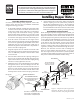


WEAR YOUR
FORESIGHT IS BETTER
THAN NO SIGHT
READ INSTRUCTIONS
BEFORE OPERATING
SAFETY GLASSES
SHERLINE PRODUCTS INC. • 3235 Executive Ridge • Vista • California 92081-8527 • FAX: (760) 727-7857
Toll Free Order Line: (800) 541-0735 • International/Local/Tech. Assistance: (760) 727-5857 • Internet: www.sherline.com
5/4/20
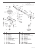
The Sherline 4" rotary table has been adapted for CNC use
with the application of a stepper motor mount in place of the
standard manual handwheel. The mount accepts a #23 frame
size stepper motor. Screws are provided for attachment of
the motor. Also included is a handwheel that can be used
on the rear shaft of a dual-shaft stepper motor if manual
control is desired for simple operations.
We have included a copy of the regular P/N 3700 rotary
table instructions. These will give you a good introduction
to using a rotary table.
Rotary Table Specifications
Backlash — ± 0.1°
Repeatability — ± 0.1°
Positioning accuracy — ± 0.1°
Horizontal orientation weight limit — 50 lbs.
Vertical orientation weight limit — 30 lbs.
Vertical rotational torque — 6 foot/lbs. (meaning it can lift a 6 lb.
weight when suspended 12" away from the center of the rotary table)
NOTE: We have stated the weight limits for our rotary tables when
under continual use. The rotary tables can hold more weight when they
are not under a continuous load.
Flats on the Motor Shafts
It is necessary to provide a at on the shaft of the stepper
motor in the proper location so that the coupler set screw
tightens on the at. If this is not done, the set screw can
distort the surface of the shaft, making it impossible to
remove from the coupler. The drawing below shows the
proper location for the at. (Note: Stepper motors purchased
from Sherline for use on Sherline CNC applications have
the ats already milled in place. Ask for P/N 67127.)
Lubrication and Maintenance
Keep your rotary table oiled to prevent rust. A few drops
of 3-in-1 oil, or a light sewing machine oil, in the oiler
before using will eliminate table wear. If you are using the
rotary table frequently, add oil once a week. The oil port
has a spring loaded steel ball
in the middle of the oil port.
With a small screw driver or
paper clip, push the ball down
to open the hole in the top of
the oiler. While pushing the
ball down, add drops of oil to
the top of the oiler. The oil
will seep down past the ball
into the oiler. After the oil has
entered the oiler port, release
the ball and it will pop back
up to seal the oiler port.
The worm gear is greased at the factory. The lubricating
grease that we apply at the factory will last a lifetime for
the average customer. In industrial use, where the rotary
table is used 24/7, it can run for a year or more before it
needs any maintenance.
Moving the worm housing to compensate for wear can
eliminate worm backlash. From the bottom of the rotary
table, loosen one of the two socket head cap screws holding
the worm housing to the table base. Lightly tap the housing
toward the table with a plastic mallet to push the worm a
little tighter into the gear teeth on the table. When backlash
is less than .2°, retighten the screw.
Using a Riser Plate on Sherline Mills
On page 4, we provide a drawing of a riser plate that will
lift the rotary table enough to clear the mill handwheel on
Sherline mills. Four mounting holes marked “A” are used to
mount it to the mill table T-slots. If used on a non-Sherline
machine, you may eliminate these holes. You may make the
plate yourself from the drawing. Sherline oers the plate
as an accessory should you wish to order one ready-made
(P/N 8710).
Thank you,
Sherline Products Inc.
Oiler Port
FIGURE 2—Oiler port
location.
FLANGE
BOSS
Optional rear
handwheel
shaft
.5 .46
2.13"
Shaft: .25" Diameter
FIGURE 1—Locations for
the ats on stepper motor
shaft.
CNC-Ready Rotary Table
P/N 3700-CNC