WEAR YOUR SAFETY GLASSES FORESIGHT IS BETTER THAN NO SIGHT READ INSTRUCTIONS BEFORE OPERATING Miniature Lathe and Milling Machine Assembly and Instruction Guide Eighth Edition P/N 5326 ©2017, Sherline Products Inc.
Full One-Year Warranty on Sherline’s 3.5" Metal Lathe, Vertical Milling Machine, and Accessories If within one year from the date of purchase a new* Sherline power tool fails due to a defect in material or workmanship, Sherline will repair it free of charge.
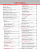
Table of Contents Safety Rules for Power Tools..............................................2 An Introduction to the World of Miniature Machining.........3 General Precautions..............................................................3 Machine Terminology...........................................................4 The Customer's Responsibility.............................................5 Learning More About Machining.........................................
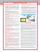
Safety Rules for Power Tools 1. Know Your Power Tool—Read the owner’s manual carefully. Learn its application and limitations as well as the specific potential hazards peculiar to this tool. 2. Ground All Tools—If a tool is equipped with a three-prong plug, it should be plugged into a three-hole receptacle. If an adapter is used to accommodate a two-prong receptacle, the adapter wire must be attached to a KNOWN GROUND. Never remove the third prong. (See Figure 1.) 3.
An Introduction to the World of Miniature Machining a time. The interesting thing is, a skilled machinist may take almost as long to make the same part as a novice. Shortcuts usually end in failure. Unlike some other trades, mistakes cannot be covered up. There are no erasers, white-out or “putting-on tools” for machinists; you simply start over.
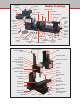
SPEED CONTROL ASSEMBLY SPEED CONTROL KNOB Machine Terminology ON/OFF SWITCH TAILSTOCK DRILL CHUCK HEADSTOCK DC MOTOR TAILSTOCK SPINDLE TOOL POST 3-JAW CHUCK TAILSTOCK SPINDLE LOCK CROSSLIDE SADDLE TAILSTOCK TAILSTOCK FEED HANDWHEEL HEADSTOCK SPINDLE “V” BELT TAILSTOCK LOCKING SCREW LATHE BED GIB ADJUSTMENT SCREWS 2-SPEED STEPPED PULLEY HEADSTOCK LOCKING SCREW LEADSCREW HANDWHEEL LATHE DRIVE DOG FACEPLATE HARD STOP HOLES SPINDLE BARS #1 MORSE HEADSTOCK CENTER #1 MORSE ARBOR #0 MORSE TA
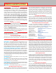
WARNING! WD-40 is a rust preventative, not a lubricant. Do not use WD-40 on your machine slides or screws as a lubricant. Avoid Overtightening! One of the problems with designing and manufacturing metal cutting equipment of this size is that the operator can physically be stronger than the machine, which is not normally the case with larger tools. For example, a 10-pound force applied a couple of inches out on a hex key becomes a 650-pound force at the tip of the screw.
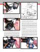
Video instructions for assembling Sherline lathes and mills can be viewed at sherline.com/sherline-videos/. FIGURE 5—Installing the crosslide table onto the saddle both machines you will need to install the motor and speed control. Some of these parts are assembled and tested for fit at the factory prior to shipping. They are then disassembled and packaged, so everything should go together easily when you reassemble it.
bottom of the base. Hand-turn the first screw part way in, and then start the second screw. This can be done with the machine upright by letting the base hang over the edge of your table or bench just far enough to expose the first hole. Using the large 3/16" hex key provided, snug up both screws lightly first, and then tighten evenly.
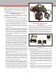
Motor Mounting Screw Speed Control Housing Pin S/C Hinge Plate Pin S/C Cover Mounting Plate Drive Belt Spindle Pulley DC Motor Headstock Spindle and Motor Mounting Bracket Assembly FIGURE 10—Place belt over motor pulley. Press the two nuts into the hex shaped depressions in the rear of the inner belt guard and secure the outer cover with two 1-3/8" pan head screws through the covers and into the nuts. Don’t fully tighten until everything is aligned.
7. Temporarily tighten the two motor mount screws. Pivot the speed control unit up and out of the way to check the alignment of the drive belt. It should be perpendicular to the drive pulleys. If not, loosen the set screw on the motor pulley and adjust it in or out on its shaft until the drive belt is square with the motor. 8. Loosen the two motor mounting screws and push the motor away from the headstock to adjust tension in the drive belt.
Removing the headstock alignment key permits the headstock to be mounted in positions other than square. This allows you to mill parts at an angle or turn tapers on the lathe. When using the lathe or mill without the alignment key, keep cutting loads light. Operation of the Motor and Electronic Speed Control The motor is supplied with current from an electronic speed control that produces a comprehensive range of speeds suitable for all operations.
CAUTION! Check the Tightness of all Bolts—Vibration in shipping can cause some bolts or screws to loosen up. Before using your new machine, check the tightness of all fasteners. It is also a good idea to check tightness periodically when using the machine, as vibration from operation may cause some fasteners to loosen up. HIGH TORQUE, LOW RPM POSITION NORMAL BELT POSITION A B FIGURE 20—The two pulley positions.
Want to see some projects built by other Sherline machinists? Visit sherline.com/workshop/. SADDLE BED Gib Adjustment (Lathe and Mill) GIB (See Figure 21) Tapered gibs are fitted to the mill headstock, saddle and table and to GIB LOCK the lathe saddle and crosslide. Correct adjustment of the gibs will ensure smooth and steady FIGURE 21—Adjusting the gibs operation of the slides. The gib is effectively a taper with an angle corresponding to the one machined into the saddle.
General questions about tools or accessories? See our “Frequently asked questions” section at sherline.com/standard-faq/. Aligning the Headstock and Tailstock on the Lathe The versatile feature of Sherline machines that allows the headstock to be removed or rotated for taper turning and angle milling keeps us from being able to lock the headstock in perfect alignment. Precision ground alignment keys and accurate adjustment at the factory, however, make the machines highly accurate.
Why Aren’t Alignment Pins Used to Square up the Machine? If you are a novice to machining, you probably believe a machine should be designed so that a couple of pins could be dropped into holes, squaring up the machine and eliminating this whole alignment process. After all, that is the way they do it with woodworking tools. The truth is the tolerances that work well for wood cutting tools simply aren’t accurate enough for most metalworking jobs. You just can’t hold the tolerances required with “pins.
WHEN SQUARE, SCRIBE ZERO REFERENCE MARK HERE FIGURE 26—Squaring up the ram parallel to the Y-axis on the 2000-series mill. The indicator can be held with a chuck on the table or a mill vise as shown here. When square, tighten the nut on top of the column. 5000/5400-series mills can be adjusted slightly by loosening the two bolts that hold the column base in place, twisting the column slightly and retightening the bolts.
ADJUST FORE/AFT MOVEMENT WITH CENTER ADJUSTMENT SCREW ON ALIGNMENT BLOCK LOCK ADJUSTMENT IN PLACE WITH 11/16" FLANGE NUT HEADSTOCK PIVOTS ON SADDLE PIN. EVEN WITH ALIGNMENT KEY IN PLACE, SLIGHT ADJUSTMENT CAN BE MADE TO GET HEADSTOCK PERFECTLY SQUARE. FIGURE 28—Squaring the fore and aft pivot movement of the column with the Y-axis. (See the hint in the section on squaring the X-axis above for a way to keep the tip of the indicator from dropping into the T-slots.) fit as closely as possible.
to the lower end of the Z-axis movement so that end mills can be brought down below the surface of the table for working on the edge of parts. This travel extension is now standard on all Model 2000 mills. The headstock may be lowered even more by placing the column top (P/N 56550) above the swing arm instead of below it. Remove the flange nut, hold-down washer and swing arm. Place the swing arm over the hold-down bolt directly on top of the column base (P/N 56660).
What is “Tool Chatter?” To see a video demonstration of what “chatter” actually sounds like and how to cure it, see the Sherline website at sherline.com/test-cuts/. The page contains short video clips of various materials from Delrin to Inconel being cut on a Sherline lathe. At the bottom of the page is a link to a video demonstration of chatter.
would be similar to tearing an individual sheet of paper off the roll. The results when cutting metal would be shorter tool life, a poor finish and tool “chatter.” Chatter is a function of rigidity, but it is controlled by speed (RPM) and feed rate. Since you already have a piece of aluminum chucked up, experiment with speed and feed rate. You just took a cut of .010" (.25 mm) and probably noticed that the machine didn’t even slow down in the slightest. Now take a 1/2 inch long cut .
the headstock by lowering it onto a block of wood extending to the table on the mill will keep from knocking the column out of alignment. TAILSTOCK—The tailstock spindle does not have a through hole and a drawbolt is not used. It is equipped with a Morse #0 taper, and accessories such as drill chucks and centers can be removed by turning the handwheel counter-clockwise until the back of the taper hits the inside of the spindle and the accessory is ejected FIGURE 37—Headstock drilling.
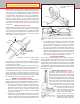
NORMAL TURNING TOOLS (SIDE TOOLS)* LEFT-HAND BORING TOOL* RIGHT-HAND INSIDE THREADING TOOL PARTING TOOL*** THREADING TOOL** (P/N 1200) * These shapes are available in high speed steel tool set, P/N 3007. ** The 60° threading tool is included as part of the carbide tool set, P/N 3006 and also comes with the thread cutting attachment (P/N 3100.) *** The parting tool comes with the cutoff tool holder, P/N 3002. Other shapes are custom ground to accomplish special purposes as needed.
NORMAL TOOL SIDE TOOLS SLIGHTLY ROUNDED CORNER CLEARANCE LEFT-HAND RIGHT-HAND TOOL TOOL CLEARANCE FIGURE 43—Arrows show direction of tool feed in all diagrams. FIGURE 41—A boring tool in use on the lathe PART FIGURE 42—Form tool and part Form Tool—A custom contour can be ground into a tool to produce a special shape like a radius in a part. The width of the cutting edge must be less than 2-1/2 TOOL times the smallest diameter. Cutting speed must be slow to prevent chatter.
FIGURE 44—A parting tool used to separate a part from it’s bar stock. If the tool chatters, first check to see if the work is being held properly. Then decrease speed (RPM) or increase feed rate or both. Once the blade has chattered, it leaves a serrated finish that causes more chatter.
New Sherline Accessories Sherline introduces new accessories every year. See our website for new product introductions. FIGURE 47—Two-Position Rocker Tool Post (P/N 7603) Another tool available to Sherline machinists that holds carbide inserts is the 1/4"–3/8" twoposition rocker tool post, P/N 7603 (See Figure 47). This tool post has slots on two opposite sides to hold both 1/4" and 3/8" square shank tools individually or at the same time.
are fitted with a #0 Morse arbor for use in the tailstock for center drilling parts. They also come with a #1 Morse arbor and drawbolt for use in the headstock on the lathe or mill. Adjustment keys are included. Chucks available include a 5/32", 1/4" and 3/8" size. 5/32" Drill Chucks—These small chucks hold tiny drills from size #80 up to 5/32". Because they have a #0 Jacobs taper in the back, the adapter arbor must be pressed in, so it is not interchangeable.
3-Jaw Chuck Operation and Maintenance The 3-jaw self-centering chuck is the most popular of all the accessories available for the Sherline lathe. It is available in both 2-1/2" diameter (P/N 1041) and 3-1/8" diameter (P/N 1040). These chucks will grip round or hexagonal work quickly, since the jaws move simultaneously to automatically center the work being held. The jaws on the chuck are designed so that the same chuck can be used for both internal and external gripping.
but there are some important design differences; for example, the mill has a spindle that can take side loads as well as end loads and an accurate method of moving work in relation to the spindle on all three axes. It is wise to memorize these “X,” “Y” and “Z” axes, because, since the advent of complex electronically controlled milling machines, these terms have become common “shop talk,” even outside engineering departments. Feed screws with calibrated handwheels control movements on these three axes.
CAUTION! Because the tool spins on a mill, hot chips can be thrown much farther than when using a lathe. Safety glasses and proper clothing are a must for all milling operations. Securing the Workpiece The first problem encountered will be holding the work and aligning it to the machine. It is important for reasons of safety and accuracy that the workpiece be solidly secured.
little as you need. The price per inch is somewhat higher than industrial rates, but the convenience and overall savings make it well worth it. There are several suppliers listed on Sherline’s website. Your local scrap yard can also be a good source for raw materials at good prices. Bring your own hacksaw, and be aware that the some yards are better than others at identifying and organizing the materials.
FIGURE 58— Boring the inside of a hole to exact size with a boring tool held in a boring head. won’t chip when a line is scribed. The purpose of this fluid is to highlight the scribed line and make it easier to see. Don’t prick-punch the scribed, crossed lines representing a hole center. Using a center drill in the mill spindle and a magnifying glass, bring the headstock down until the center drill just barely touches the scribed cross.
FIGURE 60—Indicating in the center of a hole. any error (which should be small), place a shim between the column block and the mill base. Locating the Edge of a Part in Relation to the Spindle There are two quick methods of “picking up an edge” of a part on a mill. The first is to put a shaft of known diameter in the spindle and see that it runs perfectly true. Using a depth micrometer against the edge of the part, measure the distance to the outside diameter of the shaft.
MATERIAL Stainless Steel, 303 Stainless Steel, 304 Stainless Steel, 316 Steel, 12L14 Steel, 1018 Steel, 4130 Gray Cast Iron Aluminum, 7075 Aluminum, 6061 Aluminum, 2024 Aluminum, Cast Brass Cutting Speeds for Milling Speed Adjustment Chart SPINDLE RPM = 3.82 x S.F.M. D S.F.M. = The rated Surface Feet per Minute for milling. For drilling, use 60% of the rated surface feet.
(P/N 6080), 1/4" (P/N 6079), 5/16" (P/N 3075), 6.0 mm (P/N 3076), 8.0 mm (P/N 3077) and 10 mm (P/N 3078). Drill Chuck Holder (P/N 3074) In order to allow for a quick way to change chucks, a similar holder with a 3/8-24 threaded boss on the end instead of a hole is now available. This allows 1/4" and 3/8" Jacobs drill chucks to be threaded onto a holder and changed quickly. During CNC operations this also means drills can be changed without having to change the tool length in the “tools” table.
P/N 7620 FLY CUTTER WITH CARBIDE INSERT P/N 3052 FLY CUTTER USES A 1/4" SQUARE HSS OR BRAZED CARBIDE CUTTING TOOL FIGURE 67—Fly cutters and drawbolts Fly Cutters (P/N 3052 and P/N 7620) For machining flat surfaces, fly cutters are recommended. It is imperative that the tool be used with utmost care. EYE PROTECTION IS A MUST, and the work as well as the cutting tool must be properly held.
Tilting Angle Table (P/N 3750) This accessory opens up a great variety of setup options. The table can be tilted to any angle from 0° to 90°. A hole pattern in the table is designed to easily mount the mill vise or rotary table for holding parts. A chuck adapter is included that allows the 3-jaw or 4-jaw chuck to be screwed directly to the table as well. Parts mounted to the table can be machined or drilled at precise angles without tilting the column or headstock.
FIGURE 73—P/N 8020 CNC system includes 2000 mill, motors, computer and software. To view or print complete instructions for all Sherline accessories, see sherline.com/product-information/ sherline-accessory-instructions/. CNC Rotary Indexer (P/N 8700) This completely self-contained, programmable unit is perfect for repetitive radial operations like gear cutting, drilling multiple hole patterns, cutting splines on a shaft or spokes in a wheel.
part has helped establish a new era of product design. 2. PRODUCTION—CNC can speed up the process on short run production parts. It can also take the boredom (and resulting mistakes) out of making the same part over and over again. 3. EDUCATION—If you are thinking of becoming a machinist today, you will need to know how to use CNC. Learning on an inexpensive machine is an excellent training experience with no worries about “crashing” a more expensive, high powered machine. 4.
with sufficient accuracy while maintaining a price appropriate for a machine of this size and cost. The kit can be installed on any Sherline lathe or mill, regardless of age, and is very easy to use. Three axes of movement are provided so the readout can be used when the lathe is set up as a mill with the optional vertical milling column attachment. In the lathe configuration you will use only two of the three, as the tailstock spindle feed screw is not fitted with a readout.
TOWARD THRUST COLLAR THICKER SIDE OF HOUSING FIGURE 80—Detail of the encoder housing showing direction of installation 6. LATHE: Install a new handwheel with encoder ring on the crosslide screw and leadscrew. Note that the handwheels are similar except that on the leadscrew, the numbers face away from the handwheel. On the crosslide they face toward the handwheel.
the ball bearing thrust and two washers from the collar and reinstall them in the new Z-axis thrust collar in the same order (See Figure 83). Install the new collar on the leadscrew shaft and secure it to the bed with the flat head screw. 8. Install the remaining handwheel and encoder unit onto the Z-axis leadscrew. Lift up on the saddle assembly until the washer and shoulder of the leadscrew are all the way up against the bottom of the collar.
NOTICE! THE DISPLAY DOES NOT CONVERT DIMENSIONS FROM INCH TO METRIC! The DRO reads rotary handwheel movement and converts it to a linear dimension based on a formula assuming a certain leadscrew thread pitch. The DRO must be set to agree with the leadscrews installed on your machine to provide accurate measurements. The only difference between the inch and metric packages is the number of divisions engraved into the handwheels.
A Few More Tips When in use, shield the unit from chips so they don’t accumulate around the telephone jack connections on the side. Do not use an air hose to clean the unit. A metal stand is now included with your DRO so you can stand the unit up on your workbench. This makes it easier to read while you work. If you wish to secure the box to the stand, a piece of double-sided foam tape is a good method.
4. Insert the motor shaft into the coupling, making sure the set screw is aligned with the flat. Keep the motor square to the mount so as not to flex the coupling during insertion. Loosely tighten the set screw. 5. Install three 8-32 x 3/8" socket head cap screws (SHCS) through the holes in the motor flange and into the stepper motor mount holes. Instead of a 4th screw in the four o’clock position use a tie wrap through that hole to secure the wire bundle from the motor.
A B 0298 -44- .46 Optional rear handwheel shaft 0.515 1.501 1.502 FLAT Shaft: .25" Diameter 1.775 2 If using a non-Sherline stepper motor, make sure to grind flats on the shafts as shown where the coupling and handwheel set screws contact the shaft. .5 FLANGE BOSS 2.13" SET SCREW ACCESS HOLE 1.600 2 8–32 TAPPED THRU 4 PL 2.250 JO E MARTIN JO E MARTIN JO E MARTIN DRAWN CHECKED DESIGNER DO NO T SCALE D RAWING !!! UNLESS O THERWISE SPECIFIED D IMENSIO NS ARE IN INCHES.
Replacement parts can be ordered through your dealer or directly from Sherline. If in doubt about whether you are ordering the correct part number, please contact Sherline. We will be glad to help you make sure you are selecting the proper parts for your needs. For a complete list of parts and prices see sherline.com/sherline-price-lists/.
Sherline CNC-Ready Lathe Exploded View and Part Numbers Sherline CNC-Ready Lathe Exploded and Part Numbers NOTE: Where different, Inch part first, followedView by Metric part number. NOTE: Where different, Inch part number is given first, followed by Metric part number.
SherlineManual Manual50005000-and and5400-Series 5400-SeriesVertical VerticalMilling MillingMachines Machines Sherline NOTE: Where different, Inch part number is given first, followed by Metric part number. NOTE: Where different, Inch part number is given first, followed by Metric part number.
Sherline CNC-Ready 5000- and 5400 Series Vertical Milling Machines Sherline CNC-Ready 5000- and 5400 Series Vertical Milling Machines NOTE: Where different, Inch part number is given first, followed by Metric part number. NOTE: Where different, Inch part number is given first, followed by Metric part number.
-49- 56230 56240 56010/56020 56700 56130 56770 56110 56550 56220 56400 56200 Saddle Nut Body P/N 40174 (Inch) P/N 41174 (Metric) 7.0 .69 .68 .67 .66 .65 .64 .62 .61 6.0 .63 .59 .58 .57 .56 .55 .54 .52 .51 5.0 .53 .49 .48 .47 .46 .45 .44 .42 .41 4.0 .43 .39 .38 .37 .36 .35 .34 .32 .31 3.0 .33 .29 .28 .27 .26 .25 .24 .22 .21 2.0 .23 .19 .18 .17 40177/41177 .16 .15 .14 .12 .11 1.0 .13 .9 .8 .7 .6 .5 .4 .3 .
X-Axis Slide Screw Insert Lock Screw -50- 56240 67153/67154 56700 56130 56770 56110 56550 56220 56400 56200 56230 40520 Mill Saddle Oiler Detail Y-Axis Slide Screw Insert Lock Screw 7.0 .69 .68 .67 .66 .65 .64 .62 .61 6.0 .63 .59 .58 .57 .56 .55 .54 .52 .51 5.0 .53 .49 .48 .47 .46 .45 .44 .42 .41 4.0 .43 .39 .38 .37 .36 .35 .34 .32 .31 3.0 .33 .29 .28 .27 .26 .25 .24 .22 .21 2.0 .23 .19 .18 .17 40170/41170 .16 .15 .14 .12 .11 1.0 .13 .9 .8 .7 .6 .5 .4 .3 .
40520 -51- 56230 50220 58011 50056 56140 56220 56400 56200 Saddle Nut Body P/N 40174 (Inch) P/N 41174 (Metric) 56210 56470 40177/41177 35170 WRONG 40900 40820 45070 40890/41890 40600 50280 40760 40520 50150 40520 40520 (Nylon Button) 40980 40520 50940 50190 50130/51130 40510 40820 43160 40280 34260/34270 34250 40530 43170 43360 43100 56190/56191 See Leadscrew Detail 40670 43130 40440 32100 41080 45475 (Hill House-2020) 50172/51172 R/H 40020 40040 54182 40690 40
40520 -52- 56240 58011 50056 56140 56230 40560 40550 40570 40580 56220 56400 56200 X-Axis Slide Screw Insert Lock Screw 58165 35160 35170 WRONG 40510 P/N 35170 40820 45070 40890/41890 40600 40760 40600 40820 40990 40520 50150 40520 40520 (Nylon Button) 40980 40520 50940 50190 40510 50130/51130 40820 40020 40040 43160 56192/56193 12050 (3) + 1 zip tie 43170 43360 43100 67111 41130 90080 90060 43200 (Label) 40620 (US) 40630 (UK) 40640 (Euro.
Machining Basics—Using the Handwheels P recision leadscrews and the handwheels that drive them make it possible to produce highly accurate parts on a mill or lathe. Here are some tips that should help first-time machinists get off to a good start. Handwheel Increments The handwheels on Sherline machines are marked in increments of one one-thousandth of an inch (.001") for inch models or one one-hundredth of a millimeter (.01 mm) for metric models.
Sherline’s founder, Joe Martin, put together the ultimate book for the Sherline machinist... This Book Gives You Not Just the “Hows,” But Also the “Whys” of Machining The Perfect “Next Step” Beyond this Instruction Book Right now you are holding one of the most complete instruction manuals ever given away with any machine tool, regardless of size or price. However, as complete as it is, most new machinists will have more questions than can be answered in a basic instruction guide.