
Sherline 4400 Lathes - Assembly and Instruction Guide
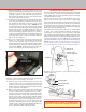
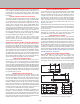
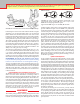
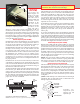
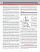
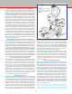
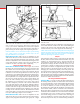
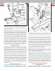
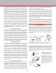
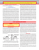
Table Of Contents
- Safety Rules for Power Tools
- An Introduction to the World of Miniature Machining
- Machine Terminology
- The Customer's Responsibility
- Learning More About Machining
- Visit the Sherline Website for the Latest Updates
- Lubrication
- Initial Assembly of a New Machine
- LATHE—Mounting the Crosslide
- All MILLS—X-Axis Handwheel Installation
- Digital Readout Handwheels
- 5000-Series Mills—Mounting the Column
- 2000- and 5800-Series Mills—Assembling and Mounting the Multi-Direction Column
- Mounting the Motor and Speed Control Unit to the Headstock
- Operation of the Motor and Electronic Speed Control
- What to Do if the Motor Suddenly Shuts Down
- Replacing Brushes on a DC Motor
- Mounting the Lathe or Mill to a Board for Stability
- Converting Machines from Inch to Metric and Vice Versa
- ADJUSTMENTS
- Two-Speed Pulley
- Spindle Preload Adjustment
- Gib Adjustment (Lathe and Mill)
- Backlash Adjustment (Lathe and Mill)
- Handwheel Adjustment (Lathe and Mill)
- Saddle Nut Adjustment (Lathe and Mill)
- Adjustment and Use of the Tailstock Gib
- Aligning the Headstock and Tailstock on the Lathe
- Squaring up Your Mill
- Use of Cutting Oils and Lubricants
- General Machining Terms
- Lathe Operating Instructions
- Digital Readouts, P/N 8200
- Live Center, P/N 1197
- Steady Rest, P/N 1074
- Thread Cutting Attachment, P/N 3100
- 3-Jaw, 4-Jaw and Drill Chucks
- Accessories for Your Lathe
- Guide to Approximate Turning Speeds
- Inserted Tip Carbide Tools
- Using the Cutoff or Parting Tool
- Tool Shapes and Grinding Your Own Cutting Tools
- Taper Turning
- Faceplate Turning
- Reaming
- Headstock Drilling
- Tailstock Drilling
- Center Drilling
- Removing Tools from the Morse Taper Spindles
- Turning Between Centers
- Holding the Workpiece
- Inducing Chatter and Learning How to Overcome It
- 3-Jaw Chuck Operation and Maintenance
- Vertical Milling Machine Operation
- Industrial Applications for Sherline Components
- Longer Tables and Taller Milling Columns Available
- Several Reasons to Consider CNC
- Learning About CNC
- CNC and CNC-Ready Sherline Lathes and Milling Machines
- CNC Rotary Indexer (P/N 8700)
- 4" Rotary Table (P/N 3700)
- Tilting Angle Table (P/N 3750)
- Mill Vise Set (P/N 3551)
- Drill Chucks (P/N 3072) and Center Drills
- Fly Cutters (P/N 3052 and P/N 7620)
- Boring Head (P/N 3054/3049)
- Mill Collet Set
- Drill Chuck Holder (P/N 3074)
- 3/8" End Mill Holder (P/N 3079)
- Accessories for Your Milling Machine
- Using the Mill Column Saddle Lock
- End Mills
- Cutting Speeds for Milling
- Determining the Depth of Cut
- Locating the Edge of a Part in Relation to the Spindle
- Using a Dial Indicator
- Standard Milling Versus Climb Milling
- Types of Milling Cutters
- Three Types of Work
- Purchasing Materials in Small Quantities
- Things to Consider Before You Start Cutting
- Locking the Axes
- Securing the Workpiece
- Helpful Tips for Milling
- General Description
- DRO Machine Operations
- Installing Stepper Motors
- Lead Wire Connection and Color Code
- Sherline Stepper Motor Specifications—Nmb Motors
- Using Handwheels on the Stepper Motors
- Stepper Motor Installation Instructions
- Sherline CNC Motor-Mounting Instructions
- Sherline Machine Technical Specifications

-9-
ALIGNMENT KEY
HEADSTOCK ASSEMBLY
PIVOT PIN
HEADSTOCK LOCKING SCREW
FIGURE 17—Headstock and alignment key in position over lathe.
Mounting the Headstock to the Lathe or Mill
You may notice that the post onto which the headstock mounts
is a loose t where it projects from the lathe bed or column
saddle. This is normal, and the diagram in Figure 16 will help
you understand how it works.
The screw in the front center of the headstock has a cone
point. The pivot pin has a tapered slot with a corresponding
angle. When the screw is tightened, its angled face engages the
groove, and, because the pivot pin can not come up, it draws
the headstock down into position, clamping it into place. If
the pin were rigid, it could keep the headstock from pulling
down squarely on the alignment key.
The headstock is aligned with the lathe bed or column saddle
by means of a precision ground key that ts into keyways
in both parts. It is not square in cross section so it will t in
only one direction. Push the headstock rmly against it as you
tighten the hold-down screw. The mill column saddle has two
keyways milled into it so the headstock can be mounted in
conventional fashion or at a 90° angle for horizontal milling.
NOTE: Alignment keys are custom tted to each machine.
If you have more than one component that uses an alignment
key, try to keep the key with the slot it was originally tted to.
FIGURE 16—A cross-section of the headstock showing the
pointed locking screw.
ALIGNMENT KEY
HEADSTOCK CASE
HEADSTOCK PIVOT PIN
HEADSTOCK LOCKING SCREW
LATHE BED
LATHE BASE
7. Temporarily tighten the two motor mount screws. Pivot
the speed control unit up and out of the way to check the
alignment of the drive belt. It should be perpendicular
to the drive pulleys. If not, loosen the set screw on the
motor pulley and adjust it in or out on its shaft until the
drive belt is square with the motor.
8. Loosen the two motor mounting screws and push the motor
away from the headstock to adjust tension in the drive
belt. Tighten the mounting screws once again to hold
the motor/speed control unit in place. (NOTE: Do not
over-tension the drive belt. Just make sure it has enough
tension to drive the spindle pulley without slipping under
normal load. By not over-tightening the belt you will
not only extend its life, but will also provide a margin of
safety for belt slippage should a tool jam in a part or an
accident occur. The belt must be a little tighter when used
in the high torque pulley range because small diameter
pulleys are not as ecient.)
9. Set the cover mounting plate into the top of the belt guard
housing so it rests on the rails molded onto the inside
surfaces of the housing. (The pressed-in nut in the
mounting plate goes down and toward the outside.) Slide
the plate toward the outside (toward the spindle pulley)
until it stops. (NOTE: The mounting plate is removable
to allow easy changing of the drive belt position.)
FIGURE 15—Insert mounting plate between belt guard halves
and secure speed control housing to nut in plate.
10. Rotate the speed control housing down into place and
insert the single 10-32 x 1/2" socket head screw through
the hole in the speed control housing and into the nut in
the mounting plate. Tighten it enough to hold the housing
in place, but do not over-tighten.
11. Make sure the power switch is in the “OFF” position and
the speed control knob is dialed all the way counter-
clockwise to the lowest speed position. Plug in the motor,
turn the On/O switch to the “ON” position and slowly
turn the speed control knob clockwise until the spindle
starts to turn. Listen and watch the belt to make sure it is
not rubbing on the belt guard or mounting tab near where
it exits the belt guard. If it is, you may need to le o a
little plastic until the belt does not rub. Turn the On/O
switch to “OFF,” unplug the motor. Headstock unit is now
ready to install on a lathe or milling machine.
CAUTION! Always make sure the key, slot and mating surfaces
are free from dirt and chips before locking down the headstock.