
Sherline 4400 Lathes - Assembly and Instruction Guide
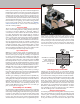
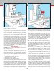
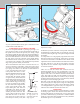
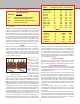
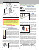
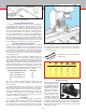
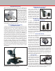
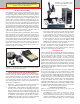
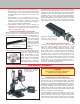
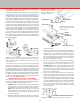
Table Of Contents
- Safety Rules for Power Tools
- An Introduction to the World of Miniature Machining
- Machine Terminology
- The Customer's Responsibility
- Learning More About Machining
- Visit the Sherline Website for the Latest Updates
- Lubrication
- Initial Assembly of a New Machine
- LATHE—Mounting the Crosslide
- All MILLS—X-Axis Handwheel Installation
- Digital Readout Handwheels
- 5000-Series Mills—Mounting the Column
- 2000- and 5800-Series Mills—Assembling and Mounting the Multi-Direction Column
- Mounting the Motor and Speed Control Unit to the Headstock
- Operation of the Motor and Electronic Speed Control
- What to Do if the Motor Suddenly Shuts Down
- Replacing Brushes on a DC Motor
- Mounting the Lathe or Mill to a Board for Stability
- Converting Machines from Inch to Metric and Vice Versa
- ADJUSTMENTS
- Two-Speed Pulley
- Spindle Preload Adjustment
- Gib Adjustment (Lathe and Mill)
- Backlash Adjustment (Lathe and Mill)
- Handwheel Adjustment (Lathe and Mill)
- Saddle Nut Adjustment (Lathe and Mill)
- Adjustment and Use of the Tailstock Gib
- Aligning the Headstock and Tailstock on the Lathe
- Squaring up Your Mill
- Use of Cutting Oils and Lubricants
- General Machining Terms
- Lathe Operating Instructions
- Digital Readouts, P/N 8200
- Live Center, P/N 1197
- Steady Rest, P/N 1074
- Thread Cutting Attachment, P/N 3100
- 3-Jaw, 4-Jaw and Drill Chucks
- Accessories for Your Lathe
- Guide to Approximate Turning Speeds
- Inserted Tip Carbide Tools
- Using the Cutoff or Parting Tool
- Tool Shapes and Grinding Your Own Cutting Tools
- Taper Turning
- Faceplate Turning
- Reaming
- Headstock Drilling
- Tailstock Drilling
- Center Drilling
- Removing Tools from the Morse Taper Spindles
- Turning Between Centers
- Holding the Workpiece
- Inducing Chatter and Learning How to Overcome It
- 3-Jaw Chuck Operation and Maintenance
- Vertical Milling Machine Operation
- Industrial Applications for Sherline Components
- Longer Tables and Taller Milling Columns Available
- Several Reasons to Consider CNC
- Learning About CNC
- CNC and CNC-Ready Sherline Lathes and Milling Machines
- CNC Rotary Indexer (P/N 8700)
- 4" Rotary Table (P/N 3700)
- Tilting Angle Table (P/N 3750)
- Mill Vise Set (P/N 3551)
- Drill Chucks (P/N 3072) and Center Drills
- Fly Cutters (P/N 3052 and P/N 7620)
- Boring Head (P/N 3054/3049)
- Mill Collet Set
- Drill Chuck Holder (P/N 3074)
- 3/8" End Mill Holder (P/N 3079)
- Accessories for Your Milling Machine
- Using the Mill Column Saddle Lock
- End Mills
- Cutting Speeds for Milling
- Determining the Depth of Cut
- Locating the Edge of a Part in Relation to the Spindle
- Using a Dial Indicator
- Standard Milling Versus Climb Milling
- Types of Milling Cutters
- Three Types of Work
- Purchasing Materials in Small Quantities
- Things to Consider Before You Start Cutting
- Locking the Axes
- Securing the Workpiece
- Helpful Tips for Milling
- General Description
- DRO Machine Operations
- Installing Stepper Motors
- Lead Wire Connection and Color Code
- Sherline Stepper Motor Specifications—Nmb Motors
- Using Handwheels on the Stepper Motors
- Stepper Motor Installation Instructions
- Sherline CNC Motor-Mounting Instructions
- Sherline Machine Technical Specifications

-34-
Fly Cutters (P/N 3052 and P/N 7620)
For machining at surfaces, y cutters are recommended.
It is imperative that the tool be used with utmost care. EYE
PROTECTION IS A MUST, and the work as well as the
cutting tool must be properly held. The big advantage of a y
cutter is its ability to take light cuts up to 2" wide and to give
an excellent surface nish. It is ideal for squaring up work.
Also, the machining stresses are lower than one might imagine,
because, unlike an end mill, very little crushing action takes
place at the cutting edge. Fly cutting tools look like left-hand
lathe tools, and, although the y cutter (P/N 3052) comes with
a brazed carbide tool, high-speed tools work quite well and
can be sharpened on any grinder. (See Figures 68 and 69.)
Drill Chucks (P/N 3072) and Center Drills
The 1/4" drill chuck available for this vertical mill is supplied
complete with a #1 Morse arbor and a drawbolt to hold it
securely in place. Drilling can be accomplished by raising and
lowering the entire head with the vertical feed handwheel. This
allows for very accurate control of feed rate and hole depth.
For accurately located holes we again stress the importance
of using center drills.
Drills should be kept in excellent condition, either by
replacement or proper resharpening. Good quality high-speed
steel drills should be employed. A dull or improperly sharpened
drill can cut oversize by as much as 10%. When you start to
drill, the initial penetration should be no more than twice the
diameter of the hole before you retract the drill, clear the chips
and add coolant with the tip of a small brush. From then on,
do not try to drill deeper than the diameter of the drill without
clearing the chips and adding coolant. For example:
To drill a 1/8" diameter hole 1" deep: Total Depth
1st Pass: 2 times diameter or 1/4" 1/4"
2nd Pass: 1 times diameter or 1/8" 3/8"
3rd Pass: 1 times diameter or 1/8" 1/2"
Etc.
(You may encounter recommendations exceeding this, but
they are meant for automatic equipment with pressurized
coolant systems.)
It is dicult to maintain tolerances of better than +.003"–.000"
with a drill. If tolerances closer than these are required, a
reamer must be employed. Try to use fractional size reamers
whenever possible rather than decimal sizes, because the
cost dierence can amount to 2 or 3 times higher for decimal
sizes. (The length of reamers may prevent their use for some
operations on machines of this size.)
Center Drills
To accurately start holes, center drills must be used. They
have a small tip that accurately starts the hole, and then the
shaft widens with a 60° cutting face to the nal diameter.
Care must be taken to employ cutting oil and to clear chips
from the drill frequently. If this is not done, the fragile tip
FIGURE 67—Fly cutters and drawbolts
P/N 3052 FLY CUTTER USES
A 1/4" SQUARE HSS OR
BRAZED CARBIDE CUTTING
TOOL
P/N 7620 FLY CUTTER
WITH CARBIDE INSERT
SIZE BODY
DIA.
DRILL
DIA.
DRILL
LENGTH
LENGTH
OVERALL
000 1/8" .020" .020" 1-1/4"
00 1/8 .025 .025 1-1/4
0 1/8 1/32 1/32 1-1/4
1 1/8 3/64 3/64 1-1/4
2 3/16 5/64 5/64 1-7/8
3 1/4 7/64 7/64 2
FIGURE 70—Table of common HSS center drill sizes.
Mill Vise Set (P/N 3551)
The vise shown here and
in use in Figures 59 and 62
is furnished with special
clamps that allow it to be
clamped in any position
on the mill table. The vise
capacity is 2 inches. It
has a movable jaw that
is pulled down while
clamping, eliminating
any chance for the jaw
to lift. Perpendicular grooves in the xed jaw help secure
round stock. It is the most convenient way to hold small parts
for milling. Also available for the mill vise is a rotating base
(P/N 3570) that greatly adds to the versatility of this basic
machining accessory.
FIGURE 68—Typical setup for y cutting.
FIGURE 69—Three center drills in the
P/N 3021 set.
may load up and twist o, even in soft materials. Center drills
are available in a variety of sizes, but for general work we
recommend size No. 1.