
Sherline 4400 Lathes - Assembly and Instruction Guide
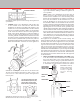
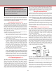
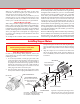
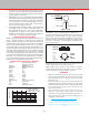
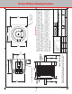
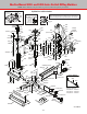
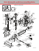
Table Of Contents
- Safety Rules for Power Tools
- An Introduction to the World of Miniature Machining
- Machine Terminology
- The Customer's Responsibility
- Learning More About Machining
- Visit the Sherline Website for the Latest Updates
- Lubrication
- Initial Assembly of a New Machine
- LATHE—Mounting the Crosslide
- All MILLS—X-Axis Handwheel Installation
- Digital Readout Handwheels
- 5000-Series Mills—Mounting the Column
- 2000- and 5800-Series Mills—Assembling and Mounting the Multi-Direction Column
- Mounting the Motor and Speed Control Unit to the Headstock
- Operation of the Motor and Electronic Speed Control
- What to Do if the Motor Suddenly Shuts Down
- Replacing Brushes on a DC Motor
- Mounting the Lathe or Mill to a Board for Stability
- Converting Machines from Inch to Metric and Vice Versa
- ADJUSTMENTS
- Two-Speed Pulley
- Spindle Preload Adjustment
- Gib Adjustment (Lathe and Mill)
- Backlash Adjustment (Lathe and Mill)
- Handwheel Adjustment (Lathe and Mill)
- Saddle Nut Adjustment (Lathe and Mill)
- Adjustment and Use of the Tailstock Gib
- Aligning the Headstock and Tailstock on the Lathe
- Squaring up Your Mill
- Use of Cutting Oils and Lubricants
- General Machining Terms
- Lathe Operating Instructions
- Digital Readouts, P/N 8200
- Live Center, P/N 1197
- Steady Rest, P/N 1074
- Thread Cutting Attachment, P/N 3100
- 3-Jaw, 4-Jaw and Drill Chucks
- Accessories for Your Lathe
- Guide to Approximate Turning Speeds
- Inserted Tip Carbide Tools
- Using the Cutoff or Parting Tool
- Tool Shapes and Grinding Your Own Cutting Tools
- Taper Turning
- Faceplate Turning
- Reaming
- Headstock Drilling
- Tailstock Drilling
- Center Drilling
- Removing Tools from the Morse Taper Spindles
- Turning Between Centers
- Holding the Workpiece
- Inducing Chatter and Learning How to Overcome It
- 3-Jaw Chuck Operation and Maintenance
- Vertical Milling Machine Operation
- Industrial Applications for Sherline Components
- Longer Tables and Taller Milling Columns Available
- Several Reasons to Consider CNC
- Learning About CNC
- CNC and CNC-Ready Sherline Lathes and Milling Machines
- CNC Rotary Indexer (P/N 8700)
- 4" Rotary Table (P/N 3700)
- Tilting Angle Table (P/N 3750)
- Mill Vise Set (P/N 3551)
- Drill Chucks (P/N 3072) and Center Drills
- Fly Cutters (P/N 3052 and P/N 7620)
- Boring Head (P/N 3054/3049)
- Mill Collet Set
- Drill Chuck Holder (P/N 3074)
- 3/8" End Mill Holder (P/N 3079)
- Accessories for Your Milling Machine
- Using the Mill Column Saddle Lock
- End Mills
- Cutting Speeds for Milling
- Determining the Depth of Cut
- Locating the Edge of a Part in Relation to the Spindle
- Using a Dial Indicator
- Standard Milling Versus Climb Milling
- Types of Milling Cutters
- Three Types of Work
- Purchasing Materials in Small Quantities
- Things to Consider Before You Start Cutting
- Locking the Axes
- Securing the Workpiece
- Helpful Tips for Milling
- General Description
- DRO Machine Operations
- Installing Stepper Motors
- Lead Wire Connection and Color Code
- Sherline Stepper Motor Specifications—Nmb Motors
- Using Handwheels on the Stepper Motors
- Stepper Motor Installation Instructions
- Sherline CNC Motor-Mounting Instructions
- Sherline Machine Technical Specifications

-39-
6. LATHE: Install a new handwheel with encoder ring
on the crosslide screw and leadscrew. Note that the
handwheels are similar except that on the leadscrew, the
numbers face away from the handwheel. On the crosslide
they face toward the handwheel. Make sure the shoulder
at the end of the leadscrew thread is seated against the
thrust collar and the handwheel is pushed in tightly to
remove end play before tightening the set screw. On the
crosslide, push the crosslide table toward the bed so that
the collar is securely against the shoulder of the leadscrew.
On the leadscrew, hold the table (not the base) with one
hand and push the handwheel onto the shaft with the other.
Rotate the handwheel so that the set screw tightens on
a new part of the shaft. If you don’t, it will tend to pick
up it’s old indentation making it dicult to tighten it in
a new position.
MILL: Install a new handwheel and encoder ring on
the X- and Y-axes. (The encoder ring has been factory
installed on the handwheel for easier assembly.) Note
that the X and Y handwheels are similar except that on
the X-axis, the numbers on the handwheel face away
from the handwheel. On the Y-axis they face toward
the handwheel. Make sure the shoulder at the end of the
leadscrew thread is seated against the thrust collar and the
handwheel is pushed in tightly to remove end play before
tightening the set screw. On the X-axis, push the table
AWAY from the handwheel while pushing the handwheel
onto the leadscrew shaft. On the Y-axis, hold the table (not
the base) with one hand and push the handwheel onto the
shaft with the other. Rotate the handwheel so that the set
screw tightens on a new part of the shaft. If you don’t, it
will tend to pick up it’s old indentation making it dicult
to tighten it in a new position.
See Figure 80 for orientation of the encoder housing. The
thicker shoulder inside the encoder should be facing toward
the thrust collar. It is easier to tighten the screws if you install
the units upside down with the screws coming down from the
top. Place the two halves of the shell over the thrust collar
and over the encoder ring and install the four #2 x 3/8" self-
tapping screws. Draw the screws down until they seat snugly,
but DO NOT OVERTIGHTEN or you will strip the threads!
Once tightened into position, the unit can be rotated around
until the screws and cable are on the bottom. When nished,
the cable from the encoders should come o to the right side
of the handwheel.
7. MILL and VERTICAL MILLING COLUMN: Using
a 1/8" hex wrench, remove the at head screw that holds
the Z-axis thrust collar to the vertical milling column.
Remove the collar by lifting it up and o the leadscrew.
If the spacer washer sticks to the bottom of it, remove
it and reinstall it on the leadscrew shaft. Then remove
FIGURE 80—Detail of the encoder housing showing direction
of installation
TOWARD THRUST COLLAR
THICKER SIDE OF HOUSING
FIGURE 81—Installing the encoder unit over the thrust collar.
The unit can be installed upside down to make it easier to put
in the screws. It is then rotated into position and tightened to
lock it in place.
1. First the shell is installed over the thrust
collar and handwheel upside down. (Left)
2. Then the shell is rotated into position
with the cable lead on the bottom. (Below)
FIGURE 82—Rotating the unit into its proper position. (Note:
Handwheel/encoder unit not shown for clarity.)
FIGURE 83—Order of
washers and bearing
in Z-axis thrust collar
on mill, or optional
vertical milling
column.
EXISTING WASHERS
AND BALL BEARING
FROM OLD COLLAR
THRUST COLLAR
P/N 8135
EXISTING WASHER
FLAT HEAD SCREW
COLUMN
LEADSCREW