
Sherline 4400 Lathes - Assembly and Instruction Guide
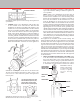
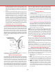
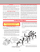
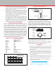
Table Of Contents
- Safety Rules for Power Tools
- An Introduction to the World of Miniature Machining
- Machine Terminology
- The Customer's Responsibility
- Learning More About Machining
- Visit the Sherline Website for the Latest Updates
- Lubrication
- Initial Assembly of a New Machine
- LATHE—Mounting the Crosslide
- All MILLS—X-Axis Handwheel Installation
- Digital Readout Handwheels
- 5000-Series Mills—Mounting the Column
- 2000- and 5800-Series Mills—Assembling and Mounting the Multi-Direction Column
- Mounting the Motor and Speed Control Unit to the Headstock
- Operation of the Motor and Electronic Speed Control
- What to Do if the Motor Suddenly Shuts Down
- Replacing Brushes on a DC Motor
- Mounting the Lathe or Mill to a Board for Stability
- Converting Machines from Inch to Metric and Vice Versa
- ADJUSTMENTS
- Two-Speed Pulley
- Spindle Preload Adjustment
- Gib Adjustment (Lathe and Mill)
- Backlash Adjustment (Lathe and Mill)
- Handwheel Adjustment (Lathe and Mill)
- Saddle Nut Adjustment (Lathe and Mill)
- Adjustment and Use of the Tailstock Gib
- Aligning the Headstock and Tailstock on the Lathe
- Squaring up Your Mill
- Use of Cutting Oils and Lubricants
- General Machining Terms
- Lathe Operating Instructions
- Digital Readouts, P/N 8200
- Live Center, P/N 1197
- Steady Rest, P/N 1074
- Thread Cutting Attachment, P/N 3100
- 3-Jaw, 4-Jaw and Drill Chucks
- Accessories for Your Lathe
- Guide to Approximate Turning Speeds
- Inserted Tip Carbide Tools
- Using the Cutoff or Parting Tool
- Tool Shapes and Grinding Your Own Cutting Tools
- Taper Turning
- Faceplate Turning
- Reaming
- Headstock Drilling
- Tailstock Drilling
- Center Drilling
- Removing Tools from the Morse Taper Spindles
- Turning Between Centers
- Holding the Workpiece
- Inducing Chatter and Learning How to Overcome It
- 3-Jaw Chuck Operation and Maintenance
- Vertical Milling Machine Operation
- Industrial Applications for Sherline Components
- Longer Tables and Taller Milling Columns Available
- Several Reasons to Consider CNC
- Learning About CNC
- CNC and CNC-Ready Sherline Lathes and Milling Machines
- CNC Rotary Indexer (P/N 8700)
- 4" Rotary Table (P/N 3700)
- Tilting Angle Table (P/N 3750)
- Mill Vise Set (P/N 3551)
- Drill Chucks (P/N 3072) and Center Drills
- Fly Cutters (P/N 3052 and P/N 7620)
- Boring Head (P/N 3054/3049)
- Mill Collet Set
- Drill Chuck Holder (P/N 3074)
- 3/8" End Mill Holder (P/N 3079)
- Accessories for Your Milling Machine
- Using the Mill Column Saddle Lock
- End Mills
- Cutting Speeds for Milling
- Determining the Depth of Cut
- Locating the Edge of a Part in Relation to the Spindle
- Using a Dial Indicator
- Standard Milling Versus Climb Milling
- Types of Milling Cutters
- Three Types of Work
- Purchasing Materials in Small Quantities
- Things to Consider Before You Start Cutting
- Locking the Axes
- Securing the Workpiece
- Helpful Tips for Milling
- General Description
- DRO Machine Operations
- Installing Stepper Motors
- Lead Wire Connection and Color Code
- Sherline Stepper Motor Specifications—Nmb Motors
- Using Handwheels on the Stepper Motors
- Stepper Motor Installation Instructions
- Sherline CNC Motor-Mounting Instructions
- Sherline Machine Technical Specifications

-41-
NOTICE! THE DISPLAY DOES NOT
CONVERT DIMENSIONS FROM INCH TO METRIC!
The DRO reads rotary handwheel movement and converts
it to a linear dimension based on a formula assuming a
certain leadscrew thread pitch. The DRO must be set to
agree with the leadscrews installed on your machine to
provide accurate measurements.
The only dierence between the inch and metric packages is
the number of divisions engraved into the handwheels. The
electronics package is the same for either and can be set to read
in either measurement system depending on the leadscrews
of the machine on which it is installed.
Setting the Backlash Compensation Values
To set backlash compensation for each axis, you must rst
measure to determine what the backlash is. Use a dial indicator
to determine how far the handwheel on each axis rotates before
the table starts to move. (If this amount is excessive, see your
instruction manual for instructions on setting backlash. It should
ideally be in the .003" to .005" range.) Once the amount is
determined, the backlash is compensated for by setting it into
the display unit’s memory.
To set the backlash to correspond to your machine’s leadscrews,
complete the following steps for each axis:
1 Turn the handwheel for each axis one full turn clockwise.
This assures that the software starts the backlash
compensation at the proper initial point.
2. Hold down the “Power” button for longer than a second
until the display changes.
3. Now you can set in the backlash for each axis by pushing
the button for that axis. Each time the button is depressed,
.0005" (or .01 mm on metric units) is added to the reading.
Set in the amount of backlash you measured previously
for each axis. Amounts up to .015" (.50 mm) can be set.
(Note: You cannot cycle backwards to a lower number.
If you go past your desired setting you must continue
pushing the button until the reading passes .015" (.50
mm) and returns to zero. Then start over.)
4. Once the backlash for all three axes is set, briey push the
“Power” button again to return the display to its normal
reading. The backlash setting can be checked or changed
at any time by holding the power button until the display
changes. The amount can then be reset as described in
instruction number 3 above. Once set, backlash settings
are held in a special memory chip even if the unit is turned
o and unplugged. They remain until you change them.
Using the DRO with the Sherline Power Feed
or Thread Cutting Attachment
The DRO leadscrew thrust collar is longer than the standard
thrust collar so that the DRO housing can attach to it. This
changes the position of the leadscrew. This has no eect on
the lathe except when it is used with a power feed or thread
cutting attachment. In those cases you will need to replace the
existing sliding engagement shaft (P/N 1509) which will be
a little too short. If you return the existing shaft to Sherline it
will be replaced at no charge with a shaft of the appropriate
length (P/N 81509) for use with the DRO. If you purchase a
new power feed or thread cutting attachment, notify Sherline
that you will be using it with the lathe DRO and the proper
shaft will be supplied with your purchase. The only alternative
to solving this problem would have been to provide a longer
leadscrew which would have been far more expensive.
Adjusting the Z-Axis Handwheel Screw
To adjust tension on the screw, rst remove all Z-axis backlash
in the conventional manner by lifting the motor/speed control
unit by hand while tightening the handwheel set screw on a
“fresh” quadrant of the leadscrew to avoid picking up any
previous indentations. Once adjusted, tighten the new center
screw only until it is “nger tight”. Use a very small amount
of Loctite
®
on the end of the screw to keep it in place. (Do
not coat the threads or the screw may become impossible to
remove.) Overtightening the screw will cause the handwheel
to become hard to turn. The purpose of the screw is not to
adjust backlash, but rather to keep it from increasing once it
is properly adjusted. Do not try to use the screw to pull out
additional backlash. The small 5-40 threads are not strong
enough for this task.
Reversing the Direction of the Reading on the X-axis
The X-axis readout is designed to read negative numbers
when the handwheel is turned in the clockwise direction and
positive when turned counter-clockwise. Should you wish to
change your readout so that it uses a standard x-y plot, you
can do so by switching two of the four wires coming from
the encoder for the X-axis.
To do so, unplug the X-axis cable from the readout box.
Remove the four screws that secure the lower housing to the
upper housing and then remove the encoder halves from the
handwheel. On the bottom of the half with the encoder is a
cover plate secured by three screws. Remove these screws and
the cover plate. This will expose the soldered connections for
the four wires coming from the encoder. To reverse the direction
of the readout, unsolder the green and black wires. Reverse
their position and re-solder to the encoder leads. Reinstall in
reverse order. The diagram below shows the factory locations
of the wires before the swap is made.
Figure 85—The drawing on the left shows the encoder housing
and wires coming from the plug. The diagram to the right shows
a schematic of where each wire is connected. Swapping the black
and green wires will change the + (plus) and – (minus) directions
of the readout.
NOTE: The wires and solder joints are small and delicate. If
you don’t have a suitable soldering iron and a little expertise
along these lines you may return your encoder housing to the
factory and we will make the change for you at no charge.
Call rst for a return authorization number and instructions
on how to return your housing.