
Sherline 4400 Lathes - Assembly and Instruction Guide
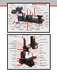
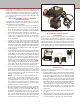
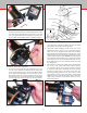
Table Of Contents
- Safety Rules for Power Tools
- An Introduction to the World of Miniature Machining
- Machine Terminology
- The Customer's Responsibility
- Learning More About Machining
- Visit the Sherline Website for the Latest Updates
- Lubrication
- Initial Assembly of a New Machine
- LATHE—Mounting the Crosslide
- All MILLS—X-Axis Handwheel Installation
- Digital Readout Handwheels
- 5000-Series Mills—Mounting the Column
- 2000- and 5800-Series Mills—Assembling and Mounting the Multi-Direction Column
- Mounting the Motor and Speed Control Unit to the Headstock
- Operation of the Motor and Electronic Speed Control
- What to Do if the Motor Suddenly Shuts Down
- Replacing Brushes on a DC Motor
- Mounting the Lathe or Mill to a Board for Stability
- Converting Machines from Inch to Metric and Vice Versa
- ADJUSTMENTS
- Two-Speed Pulley
- Spindle Preload Adjustment
- Gib Adjustment (Lathe and Mill)
- Backlash Adjustment (Lathe and Mill)
- Handwheel Adjustment (Lathe and Mill)
- Saddle Nut Adjustment (Lathe and Mill)
- Adjustment and Use of the Tailstock Gib
- Aligning the Headstock and Tailstock on the Lathe
- Squaring up Your Mill
- Use of Cutting Oils and Lubricants
- General Machining Terms
- Lathe Operating Instructions
- Digital Readouts, P/N 8200
- Live Center, P/N 1197
- Steady Rest, P/N 1074
- Thread Cutting Attachment, P/N 3100
- 3-Jaw, 4-Jaw and Drill Chucks
- Accessories for Your Lathe
- Guide to Approximate Turning Speeds
- Inserted Tip Carbide Tools
- Using the Cutoff or Parting Tool
- Tool Shapes and Grinding Your Own Cutting Tools
- Taper Turning
- Faceplate Turning
- Reaming
- Headstock Drilling
- Tailstock Drilling
- Center Drilling
- Removing Tools from the Morse Taper Spindles
- Turning Between Centers
- Holding the Workpiece
- Inducing Chatter and Learning How to Overcome It
- 3-Jaw Chuck Operation and Maintenance
- Vertical Milling Machine Operation
- Industrial Applications for Sherline Components
- Longer Tables and Taller Milling Columns Available
- Several Reasons to Consider CNC
- Learning About CNC
- CNC and CNC-Ready Sherline Lathes and Milling Machines
- CNC Rotary Indexer (P/N 8700)
- 4" Rotary Table (P/N 3700)
- Tilting Angle Table (P/N 3750)
- Mill Vise Set (P/N 3551)
- Drill Chucks (P/N 3072) and Center Drills
- Fly Cutters (P/N 3052 and P/N 7620)
- Boring Head (P/N 3054/3049)
- Mill Collet Set
- Drill Chuck Holder (P/N 3074)
- 3/8" End Mill Holder (P/N 3079)
- Accessories for Your Milling Machine
- Using the Mill Column Saddle Lock
- End Mills
- Cutting Speeds for Milling
- Determining the Depth of Cut
- Locating the Edge of a Part in Relation to the Spindle
- Using a Dial Indicator
- Standard Milling Versus Climb Milling
- Types of Milling Cutters
- Three Types of Work
- Purchasing Materials in Small Quantities
- Things to Consider Before You Start Cutting
- Locking the Axes
- Securing the Workpiece
- Helpful Tips for Milling
- General Description
- DRO Machine Operations
- Installing Stepper Motors
- Lead Wire Connection and Color Code
- Sherline Stepper Motor Specifications—Nmb Motors
- Using Handwheels on the Stepper Motors
- Stepper Motor Installation Instructions
- Sherline CNC Motor-Mounting Instructions
- Sherline Machine Technical Specifications

-4-
FIGURE 2—Lathe part terminology
DC MOTOR
HEADSTOCK
SPINDLE
“V” BELT
2-SPEED
STEPPED PULLEY
FACEPLATE
HARD STOP
HOLES
LATHE DRIVE DOG
HEX KEYS
CROSSLIDE FEED HANDWHEEL
LATHE BASE
SPEED CONTROL
ASSEMBLY
HEADSTOCK
#1 MORSE
HEADSTOCK CENTER
TOOL POST
CROSSLIDE
SADDLE
LATHE BED
#0 MORSE TAILSTOCK
CENTER
TAILSTOCK SPINDLE
TAILSTOCK
HEADSTOCK
LOCKING SCREW
SADDLE NUT
ADJUSTMENT SCREWS
Z-AXIS
LOCKING LEVER
(Located beneath saddle on
Z-Axis Leadscrew)
TAILSTOCK FEED
HANDWHEEL
TAILSTOCK
LOCKING
SCREW
LEADSCREW
HANDWHEEL
TAILSTOCK DRILL CHUCK
DRAWBOLT AND
WASHER
#1 MORSE
ARBOR
CHUCK KEY
SPINDLE BARS
SPEED CONTROL KNOB
ON/OFF SWITCH
TAILSTOCK SPINDLE LOCK
3-JAW CHUCK
BRASS
TAILSTOCK
GIB
MOUNTING
HOLES
Machine Terminology
FIGURE 3—Milling machine part terminology
VERTICAL FEED HANDWHEEL
(Z-AXIS)
2-SPEED STEPPED PULLEY
“V” DRIVE BELT
COLUMN SADDLE LOCKING LEVER
(Located behind saddle
on Z-Axis Leadscrew)
HEADSTOCK LOCKING SET SCREW
HEADSTOCK
Z-AXIS COLUMN BED
TABLE T-SLOTS (2)
SADDLE FRICTION ADJUSTMENT
SCREW (Y-AXIS LOCK) Y-AXIS GIB MILL BASE
TABLE SADDLE
X-Y AXES OILER
DC MOTOR
SPEED CONTROL ASSEMBLY
ON/OFF SWITCH
SPINDLE
TABLE
TABLE FEED HANDWHEEL
(X-AXIS)
TABLE LOCK (X-AXIS)
TABLE FEED HANDWHEEL
(Y-AXIS)
DRILL CHUCK
VARIABLE SPEED CONTROL KNOB
COLUMN BASE
HEADSTOCK ALIGNMENT KEY
Z-AXIS GIB
ADJUSTABLE ZERO HANDWHEEL
COLLAR LOCKING NUT
X-AXIS STOP SCREW
Y-AXIS ANTI-BACKLASH NUT
AND LOCK
HEADSTOCK SPACER BLOCK
Z-AXIS OILER
(Located behind column)
MOUNTING HOLE
LEADSCREW COVER
MOUNTING HOLE
GIB
ADJUSTMENT
SCREWS